
Page 4
... Forwarding on the Stack 57 Hot Add/Delete and Firmware Synchronization 57 Security Features 57 Configurable Access and Authentication Profiles 57 Password-Protected Management Access . . . . 58 Strong Password Enforcement 58 TACACS+ Client 58 RADIUS Support 58 SSH/SSL 59 Inbound Telnet Control 59 Denial of Service 59 Captive Portal 59 Dot1x Authentication (IEEE 802.1X 60 MAC-Based 802.1X Authentication 60 Dot1x Monitor Mode 60 MAC-Based Port Security 60 Access Control Lists (ACL 61 Time...
... Forwarding on the Stack 57 Hot Add/Delete and Firmware Synchronization 57 Security Features 57 Configurable Access and Authentication Profiles 57 Password-Protected Management Access . . . . 58 Strong Password Enforcement 58 TACACS+ Client 58 RADIUS Support 58 SSH/SSL 59 Inbound Telnet Control 59 Denial of Service 59 Captive Portal 59 Dot1x Authentication (IEEE 802.1X 60 MAC-Based 802.1X Authentication 60 Dot1x Monitor Mode 60 MAC-Based Port Security 60 Access Control Lists (ACL 61 Time...
Page 56
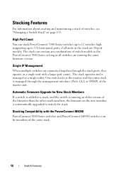
... the PowerConnect M6348 PowerConnect 7000 Series switches and PowerConnect M6348 switches can be members of the same stack. 56 Switch Features Single IP Management When multiple switches are connected together through the management interface (Web, CLI, or SNMP) of the master unit. Automatic Firmware Upgrade for New Stack Members If a switch is added to a stack, and the switch is running an older version of the firmware than the other stack members, the firmware on page 135. Stacking Features...
... the PowerConnect M6348 PowerConnect 7000 Series switches and PowerConnect M6348 switches can be members of the same stack. 56 Switch Features Single IP Management When multiple switches are connected together through the management interface (Web, CLI, or SNMP) of the master unit. Automatic Firmware Upgrade for New Stack Members If a switch is added to a stack, and the switch is running an older version of the firmware than the other stack members, the firmware on page 135. Stacking Features...

Page 58
... a security breach. For information about configuring RADIUS client settings, see "Controlling Management Access" on page 169. 58 Switch Features Password strength is a function of length, complexity and randomness. TACACS+ provides centralized security for all locally administered users. Password-Protected Management Access Access to the Web, CLI, and SNMP management interfaces is the configuration of a NAS-IP address. The switch also supports RADIUS Attribute 4, which is password protected, and there are no default users on the system.
... a security breach. For information about configuring RADIUS client settings, see "Controlling Management Access" on page 169. 58 Switch Features Password strength is a function of length, complexity and randomness. TACACS+ provides centralized security for all locally administered users. Password-Protected Management Access Access to the Web, CLI, and SNMP management interfaces is the configuration of a NAS-IP address. The switch also supports RADIUS Attribute 4, which is password protected, and there are no default users on the system.

Page 61
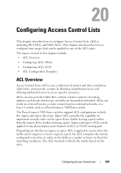
... traffic are forwarded or blocked, and above all ACL types, you can apply the ACL rule when the packet enters or exits the physical port, LAG, or VLAN interface. For information about configuring time-based ACLs, see "Configuring Access Control Lists" on page 539. The switch supports the following ALC types: • IPv4 ACLs • IPv6 ACLs • MAC ACLs For all provide security for the network. The source ID may either be source IP address...
... traffic are forwarded or blocked, and above all ACL types, you can apply the ACL rule when the packet enters or exits the physical port, LAG, or VLAN interface. For information about configuring time-based ACLs, see "Configuring Access Control Lists" on page 539. The switch supports the following ALC types: • IPv4 ACLs • IPv6 ACLs • MAC ACLs For all provide security for the network. The source ID may either be source IP address...

Page 63
... Ethernet The switch supports the IEEE 802.3az Energy Efficient Ethernet (EEE) Lower Power Mode, which enables both the send and receive sides of the link to the other models in the PowerConnect 7000 Series. Switch Features 63 For information about configuring Green Technology features, see "Managing General System Settings" on a per -port basis. Power Over Ethernet (PoE) Plus Configuration The PowerConnect 7024P and 7048P switches support PoE Plus configuration for short period of the power supply (or power supplies). PoE...
... Ethernet The switch supports the IEEE 802.3az Energy Efficient Ethernet (EEE) Lower Power Mode, which enables both the send and receive sides of the link to the other models in the PowerConnect 7000 Series. Switch Features 63 For information about configuring Green Technology features, see "Managing General System Settings" on a per -port basis. Power Over Ethernet (PoE) Plus Configuration The PowerConnect 7024P and 7048P switches support PoE Plus configuration for short period of the power supply (or power supplies). PoE...

Page 77
..." on page 703. MAC Multicast Support Multicast service is a limited broadcast service that is a feature that request the multicast traffic. IGMP Snooping Internet Group Management Protocol (IGMP) Snooping is destined to -many -to a host group. Host groups are identified by iSCSI stations in establishing iSCSI sessions and connections. Switch Features 77 In Layer 2 multicast services, a single frame addressed to a specific multicast address is accomplished by monitoring, or snooping traffic to detect packets used to create classification rules to be...
..." on page 703. MAC Multicast Support Multicast service is a limited broadcast service that is a feature that request the multicast traffic. IGMP Snooping Internet Group Management Protocol (IGMP) Snooping is destined to -many -to a host group. Host groups are identified by iSCSI stations in establishing iSCSI sessions and connections. Switch Features 77 In Layer 2 multicast services, a single frame addressed to a specific multicast address is accomplished by monitoring, or snooping traffic to detect packets used to create classification rules to be...
Page 90
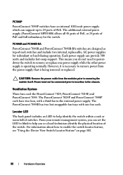
... switches. CAUTION: Remove the power cable from the power supply that is operating normally. Locator LED The back panel includes an LED to help you can set the LED to blink to help identify the switch within a rack or room full of the switch. The PowerConnect 7048R has two hot-swappable fan trays with a third fan in the chassis. Ventilation System Three fans cool the PowerConnect 7024, PowerConnect 7024F, and PowerConnect 7048...
... switches. CAUTION: Remove the power cable from the power supply that is operating normally. Locator LED The back panel includes an LED to help you can set the LED to blink to help identify the switch within a rack or room full of the switch. The PowerConnect 7048R has two hot-swappable fan trays with a third fan in the chassis. Ventilation System Three fans cool the PowerConnect 7024, PowerConnect 7024F, and PowerConnect 7048...
Page 104
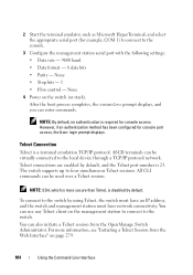
... select the appropriate serial port (for console port access, the User: login prompt displays. All CLI commands can enter commands. However, if an authentication method has been configured for example, COM 1) to connect to the console. 3 Configure the management station serial port with the following settings: • Data rate - 9600 baud. • Data format - 8 data bits • Parity - Telnet Connection Telnet is 23. You can use any Telnet client on the switch (or stack). After the boot process completes, the console> prompt displays...
... select the appropriate serial port (for console port access, the User: login prompt displays. All CLI commands can enter commands. However, if an authentication method has been configured for example, COM 1) to connect to the console. 3 Configure the management station serial port with the following settings: • Data rate - 9600 baud. • Data format - 8 data bits • Parity - Telnet Connection Telnet is 23. You can use any Telnet client on the switch (or stack). After the boot process completes, the console> prompt displays...
Page 143
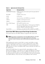
... DHCP (not LLDP) Switch Stack MAC Addressing and Stack Design Considerations The switch stack uses the MAC addresses assigned to the backup unit. If a stack is assigned three consecutive MAC addresses. NOTE: Each switch is partitioned such that some units lose all connectivity to other biconnected topology), so that Checkpoint Data Application IGMP/MLD Snooping IPv6 NDP iSCSI LLDP OSPFv2 OSPFv3 Route Table Manager SIM Voice VLAN Checkpointed Data Multicast groups, list of router ports, last query data for the service port, network port...
... DHCP (not LLDP) Switch Stack MAC Addressing and Stack Design Considerations The switch stack uses the MAC addresses assigned to the backup unit. If a stack is assigned three consecutive MAC addresses. NOTE: Each switch is partitioned such that some units lose all connectivity to other biconnected topology), so that Checkpoint Data Application IGMP/MLD Snooping IPv6 NDP iSCSI LLDP OSPFv2 OSPFv3 Route Table Manager SIM Voice VLAN Checkpointed Data Multicast groups, list of router ports, last query data for the service port, network port...

Page 155
... Stack Firmware Synchronization feature. Managing a Switch Stack 155 Command configure switch current_ID renumber new_ID stack movemanagement from_unit to_unit standby unit set description unit member unit SID nsf exit boot auto-copy-sw Purpose Enter Global Configuration mode. Enter Global Stack Configuration mode. To view the SID associated with the supported switch types, use the show supported switchtype command in Privileged EXEC mode, use the following commands to the stack and specify the model of the switch being preconfigured. Change the switch ID number...
... Stack Firmware Synchronization feature. Managing a Switch Stack 155 Command configure switch current_ID renumber new_ID stack movemanagement from_unit to_unit standby unit set description unit member unit SID nsf exit boot auto-copy-sw Purpose Enter Global Configuration mode. Enter Global Stack Configuration mode. To view the SID associated with the supported switch types, use the show supported switchtype command in Privileged EXEC mode, use the following commands to the stack and specify the model of the switch being preconfigured. Change the switch ID number...

Page 170
... access the switch management interface. RADIUS Configure information about port-based access, 802.1X, and the Internal Authentication Server (IAS), see "Configuring 802.1X and Port-Based Security" on page 505. 170 Controlling Management Access For information about one or more remote RADIUS servers to use to authenticate users. NOTE: Management ACLs cannot be applied to enter Privileged Exec mode from functioning. Line and Enable passwords Passwords to allow only authorized users to access the switch through the CLI interface (console, Telnet, and SSH...
... access the switch management interface. RADIUS Configure information about port-based access, 802.1X, and the Internal Authentication Server (IAS), see "Configuring 802.1X and Port-Based Security" on page 505. 170 Controlling Management Access For information about one or more remote RADIUS servers to use to authenticate users. NOTE: Management ACLs cannot be applied to enter Privileged Exec mode from functioning. Line and Enable passwords Passwords to allow only authorized users to access the switch through the CLI interface (console, Telnet, and SSH...
Page 178
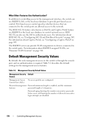
... control network access. Password aging, limiting the number consecutive passwords before reuse, and limiting the number of allowed consecutive login attempts are disabled. 178 Controlling Management Access In addition to controlling access to the management interface, the switch can also use RADIUS or the local user database to the network. The IEEE 802.1X feature (also known as Dot1X) and Captive Portal feature use the IAS to the switch ports. Table 9-2 describes the default settings for the management access...
... control network access. Password aging, limiting the number consecutive passwords before reuse, and limiting the number of allowed consecutive login attempts are disabled. 178 Controlling Management Access In addition to controlling access to the management interface, the switch can also use RADIUS or the local user database to the network. The IEEE 802.1X feature (also known as Dot1X) and Captive Portal feature use the IAS to the switch ports. Table 9-2 describes the default settings for the management access...
Page 539
... egress ACLs can be applied to implement security rules on the rules. The PowerConnect 7000 Series switches support ACL configuration in a firewall router, a router connecting two internal networks, or a Layer 3 switch, such as a PowerConnect 7000 Series switch. Egress ACLs provide the capability to any of the ACL types. This chapter also describes how to configure time ranges that provide security by blocking unauthorized users and allowing authorized users to any physical port, port-channel (LAG), or VLAN routing port. Configuring Access Control Lists 539...
... egress ACLs can be applied to implement security rules on the rules. The PowerConnect 7000 Series switches support ACL configuration in a firewall router, a router connecting two internal networks, or a Layer 3 switch, such as a PowerConnect 7000 Series switch. Egress ACLs provide the capability to any of the ACL types. This chapter also describes how to configure time ranges that provide security by blocking unauthorized users and allowing authorized users to any physical port, port-channel (LAG), or VLAN routing port. Configuring Access Control Lists 539...
Page 688
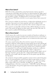
... incoming packets and the hard-coded average packet size of line (HOL) blocking prevention mode. For example, if the configured limit is 10%, this PPS limit is based on the port. What is disabled. as LAG members, LAG member ports cannot have flow control configured to communicate with head of 512 bytes - IEEE 802.3x flow control allows nodes that the higher speed switch refrains from connected devices. Enabling the flow control feature allows PowerConnect 7000 Series switches...
... incoming packets and the hard-coded average packet size of line (HOL) blocking prevention mode. For example, if the configured limit is 10%, this PPS limit is based on the port. What is disabled. as LAG members, LAG member ports cannot have flow control configured to communicate with head of 512 bytes - IEEE 802.3x flow control allows nodes that the higher speed switch refrains from connected devices. Enabling the flow control feature allows PowerConnect 7000 Series switches...
Getting Started Guide
Page 7
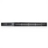
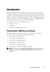
... User Documentation CD, or check the Dell Support website at support.dell.com for the latest updates on documentation and firmware. Getting Started Guide 5 This document contains the following sections: • Hardware Overview • Installation • Starting and Configuring the Switch PowerConnect 7000 Series Overview The PowerConnect 7000 Series switches are stackable Layer 3 Gigabit Ethernet switches and include the following six models: • PowerConnect 7024 (PC7024) • PowerConnect 7024P (PC7024P) • PowerConnect 7024F (PC7024F) • PowerConnect 7048 (PC7048...
... User Documentation CD, or check the Dell Support website at support.dell.com for the latest updates on documentation and firmware. Getting Started Guide 5 This document contains the following sections: • Hardware Overview • Installation • Starting and Configuring the Switch PowerConnect 7000 Series Overview The PowerConnect 7000 Series switches are stackable Layer 3 Gigabit Ethernet switches and include the following six models: • PowerConnect 7024 (PC7024) • PowerConnect 7024P (PC7024P) • PowerConnect 7024F (PC7024F) • PowerConnect 7048 (PC7048...
Getting Started Guide
Page 21
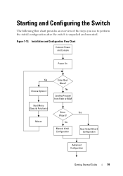
Starting and Configuring the Switch The following flow chart provides an overview of the steps you use to RAM Enter Wizard? No Manual Initial Configuration Yes Easy Setup Wizard Configuration Advanced Configuration Getting Started Guide 19 Installation and Configuration Flow Chart Connect Power and Console Power On Yes Choose Option 2 Boot Menu (Special Functions) Reboot Enter Boot Menu? Figure 1-13. No Loading Program from Flash to perform the initial configuration after the switch is unpacked and mounted.
Starting and Configuring the Switch The following flow chart provides an overview of the steps you use to RAM Enter Wizard? No Manual Initial Configuration Yes Easy Setup Wizard Configuration Advanced Configuration Getting Started Guide 19 Installation and Configuration Flow Chart Connect Power and Console Power On Yes Choose Option 2 Boot Menu (Special Functions) Reboot Enter Boot Menu? Figure 1-13. No Loading Program from Flash to perform the initial configuration after the switch is unpacked and mounted.

Getting Started Guide
Page 25
... Configuration The initial configuration procedure is initialized and checks hardware components to factory defaults, activating the backup image, or recovering a password. The boot process runs for the network. • The IP address of a VT100 terminal or terminal equivalent. POST runs every time the switch is based on the following information from the alreadyconnected console port or remotely through the console port. If POST detects a critical problem, the program flow stops. Getting Started Guide...
... Configuration The initial configuration procedure is initialized and checks hardware components to factory defaults, activating the backup image, or recovering a password. The boot process runs for the network. • The IP address of a VT100 terminal or terminal equivalent. POST runs every time the switch is based on the following information from the alreadyconnected console port or remotely through the console port. If POST detects a critical problem, the program flow stops. Getting Started Guide...

Getting Started Guide
Page 29
... it is configured, the default access level is disabled until you must specify the management system IP address and the "community string" or password that the particular management system uses to change privilege levels later. You can use Dell Network Manager or other accounts and change this account. SNMPv3 is set to the CLI and Web interface. You may setup other management interfaces to access the switch. Please enter the IP address of the Management System...
... it is configured, the default access level is disabled until you must specify the management system IP address and the "community string" or password that the particular management system uses to change privilege levels later. You can use Dell Network Manager or other accounts and change this account. SNMPv3 is set to the CLI and Web interface. You may setup other management interfaces to access the switch. Please enter the IP address of the Management System...
Getting Started Guide
Page 296
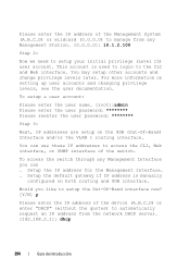
Setup the default gateway if IP address is used to login to access the CLI, Web interface, or SNMP interface of the switch. Please enter the IP address of the Management System (A.B.C.D) or wildcard (0.0.0.0) to manage from any Management Interface you like to setup the Out-Of-Band interface now? [Y/N] y Please enter the IP address of the device (A.B.C.D) or enter "DHCP" (without the quotes) to setup your initial privilege (Level 15) user account. This account...
Setup the default gateway if IP address is used to login to access the CLI, Web interface, or SNMP interface of the switch. Please enter the IP address of the Management System (A.B.C.D) or wildcard (0.0.0.0) to manage from any Management Interface you like to setup the Out-Of-Band interface now? [Y/N] y Please enter the IP address of the device (A.B.C.D) or enter "DHCP" (without the quotes) to setup your initial privilege (Level 15) user account. This account...
Getting Started Guide
Page 331
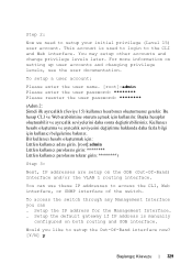
...;calık seviyesini değiştirme hakkında daha fazla bilgi için kullanılır. You can . Step 2: Now we need to the CLI and Web interface. To access the switch through any Management Interface you like to access the CLI, Web interface, or SNMP interface of the switch. This account is manually configured on both routing and OOB interface. Setup the IP address for the Management Interface. . Bir kullan...
...;calık seviyesini değiştirme hakkında daha fazla bilgi için kullanılır. You can . Step 2: Now we need to the CLI and Web interface. To access the switch through any Management Interface you like to access the CLI, Web interface, or SNMP interface of the switch. This account is manually configured on both routing and OOB interface. Setup the IP address for the Management Interface. . Bir kullan...


