
Command Line Interface (CLI) Guide (.htm)
Page 244
...that operating the powered device is attached to the interface. Example The following example configures a description to an IP-phone to a powered device connected to Ethernet interface 1/e1. FOR PROOF ONLY 244 Power over Ethernet Commands Syntax power inline powered-device pd-type ...the no power inline priority • critical - To return to the default configuration, use the no power inline powered-device • pd-type-Specifies the type of the interface. www.dell.com | support.dell.com power inline powered-device The power inline powered-device Interface Configuration (Ethernet)...
...that operating the powered device is attached to the interface. Example The following example configures a description to an IP-phone to a powered device connected to Ethernet interface 1/e1. FOR PROOF ONLY 244 Power over Ethernet Commands Syntax power inline powered-device pd-type ...the no power inline priority • critical - To return to the default configuration, use the no power inline powered-device • pd-type-Specifies the type of the interface. www.dell.com | support.dell.com power inline powered-device The power inline powered-device Interface Configuration (Ethernet)...
Command Line Interface (CLI) Guide (.htm)
Page 245
... following example configures the device connected to Ethernet interface 1/e1 as a percentage to compare measured power. (Range: 1-99) Default Configuration The default threshold is low priority. Syntax power inline usage-threshold percentage no power inline usage-threshold • percentage-Specifies the threshold as a highpriority powered device. PRELIMINARY 9/13/06 - FOR PROOF ONLY Power over Ethernet Commands 245 DELL CONFIDENTIAL...
... following example configures the device connected to Ethernet interface 1/e1 as a percentage to compare measured power. (Range: 1-99) Default Configuration The default threshold is low priority. Syntax power inline usage-threshold percentage no power inline usage-threshold • percentage-Specifies the threshold as a highpriority powered device. PRELIMINARY 9/13/06 - FOR PROOF ONLY Power over Ethernet Commands 245 DELL CONFIDENTIAL...
User's Guide (.htm)
Page 4
... the Device 50 Installing in a Rack 50 Installing on a Flat Surface 51 Installing the Device on a Wall 52 Connecting to a Terminal 53 Connecting a Device to a Power Supply 54 Installing a Stack 54 Overview 54 Stacking PowerConnect 3400 Series Switches 54 Unit ID Selection Process 56 Starting and Configuring the Device 57 Connecting to the Device 57 4 Contents
... the Device 50 Installing in a Rack 50 Installing on a Flat Surface 51 Installing the Device on a Wall 52 Connecting to a Terminal 53 Connecting a Device to a Power Supply 54 Installing a Stack 54 Overview 54 Stacking PowerConnect 3400 Series Switches 54 Unit ID Selection Process 56 Starting and Configuring the Device 57 Connecting to the Device 57 4 Contents
User's Guide (.htm)
Page 10
... Port LEDs 43 System LEDs 44 Stacking LEDs 45 Power Connection 46 Bracket Installation for Rack Mounting 51 Bracket Installation for Mounting on a Wall . . . . . 52 Mounting a Device on a Wall 53 Back-Panel Power Connector 54 Stacking Cable Diagram 55 Stacking Configuration and Identification Panel . . . 56 Connecting to PowerConnect 3400 Series Console Port 58 10 Contents Figure...
... Port LEDs 43 System LEDs 44 Stacking LEDs 45 Power Connection 46 Bracket Installation for Rack Mounting 51 Bracket Installation for Mounting on a Wall . . . . . 52 Mounting a Device on a Wall 53 Back-Panel Power Connector 54 Stacking Cable Diagram 55 Stacking Configuration and Identification Panel . . . 56 Connecting to PowerConnect 3400 Series Console Port 58 10 Contents Figure...
User's Guide (.htm)
Page 39
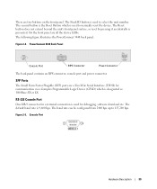
RS-232 Console Port One DB-9 connector for a terminal connection is used to 115,200 bps. The Stack ID button is used for communication via a Complex Programmable Logic Device (CPLD) which is designated as 1000Base-... (TWSI) for debugging, software download etc. The baud rate can be configured from 2400 bps up to manually reset the device. Figure 2-5. PowerConnect 3448 Back Panel Console Port RPS Connector Power Connector The back panel contains an RPS connector, console port and power connector. The second button is the Reset Button which is used...
RS-232 Console Port One DB-9 connector for a terminal connection is used to 115,200 bps. The Stack ID button is used for communication via a Complex Programmable Logic Device (CPLD) which is designated as 1000Base-... (TWSI) for debugging, software download etc. The baud rate can be configured from 2400 bps up to manually reset the device. Figure 2-5. PowerConnect 3448 Back Panel Console Port RPS Connector Power Connector The back panel contains an RPS connector, console port and power connector. The second button is the Reset Button which is used...
User's Guide (.htm)
Page 46
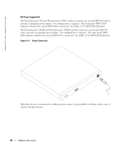
www.dell.com | support.dell.com DC Power Supply Unit The PowerConnect 3424 and PowerConnect 3448 switches connect to an external RPS-600 unit to provide a redundant power option. No configuration is required. No configuration is required. Figure 2-11. Power Connection When the device is connected. See Table 2-5 for RPS LED definition. The front panel "RPS" LED indicates whether the external EPS-470...
www.dell.com | support.dell.com DC Power Supply Unit The PowerConnect 3424 and PowerConnect 3448 switches connect to an external RPS-600 unit to provide a redundant power option. No configuration is required. No configuration is required. Figure 2-11. Power Connection When the device is connected. See Table 2-5 for RPS LED definition. The front panel "RPS" LED indicates whether the external EPS-470...
User's Guide (.htm)
Page 54
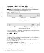
... Console Port EPS Connector PowerConnect 3424P/3448P Rear View Power Connector After connecting the device to a grounded AC outlet at this time. All stacks must have a Master unit, and may have a Master Backup unit, with any other devices connected to 192 ports are considered stacking Members. 54 Installing the PowerConnect 3424/P and PowerConnect 3448/P Figure 3-4. Installing a Stack...
... Console Port EPS Connector PowerConnect 3424P/3448P Rear View Power Connector After connecting the device to a grounded AC outlet at this time. All stacks must have a Master unit, and may have a Master Backup unit, with any other devices connected to 192 ports are considered stacking Members. 54 Installing the PowerConnect 3424/P and PowerConnect 3448/P Figure 3-4. Installing a Stack...
User's Guide (.htm)
Page 56
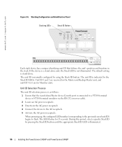
...ID button until the appropriate Stack ID LED is stand-alone. The default setting is illuminated. 56 Installing the PowerConnect 3424/P and PowerConnect 3448/P When powering up, the configured LED number (corresponding to the previously saved unit ID) begins to 6 are reserved for 15 seconds. The unit... identifying unit ID that the stand-alone/Master device Console port is not illuminated. www.dell.com | support.dell.com Figure 3-6. If the device is a stand-alone unit, the Stack LED is connected to a VT100 terminal device or VT100 terminal emulator via the RS-232 crossover cable. ...
...ID button until the appropriate Stack ID LED is stand-alone. The default setting is illuminated. 56 Installing the PowerConnect 3424/P and PowerConnect 3448/P When powering up, the configured LED number (corresponding to the previously saved unit ID) begins to 6 are reserved for 15 seconds. The unit... identifying unit ID that the stand-alone/Master device Console port is not illuminated. www.dell.com | support.dell.com Figure 3-6. If the device is a stand-alone unit, the Stack LED is connected to a VT100 terminal device or VT100 terminal emulator via the RS-232 crossover cable. ...
User's Guide (.htm)
Page 57
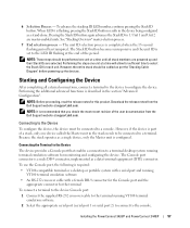
...and Unit 2 are selected. However, the entire stack should be connected to a terminal. Starting and Configuring the Device After completing all stack members are powered up the devices. Connecting to be performed one unit at support.dell.com. The Console port connector is a male DB-9 connector, ...connections, connect a terminal to the device to the terminal running VT100 terminal emulation software • An RS-232 crossover cable with a female DB-9 connector for the Console port and the appropriate connector for this product. Installing the PowerConnect 3424/P and PowerConnect ...
...and Unit 2 are selected. However, the entire stack should be connected to a terminal. Starting and Configuring the Device After completing all stack members are powered up the devices. Connecting to be performed one unit at support.dell.com. The Console port connector is a male DB-9 connector, ...connections, connect a terminal to the device to the terminal running VT100 terminal emulation software • An RS-232 crossover cable with a female DB-9 connector for the Console port and the appropriate connector for this product. Installing the PowerConnect 3424/P and PowerConnect ...
User's Guide (.htm)
Page 60
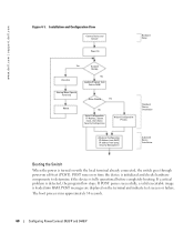
... is detected, the program flow stops. The boot process runs approximately 30 seconds. 60 Configuring PowerConnect 3424/P and 3448/P POST runs every time the device is initialized and checks hardware components...power-on the terminal and indicate test success or failure. Installation and Configuration Flow Connect Device and Console Power On Hardware Setup Press Esc Yes Susepnd Bootup No Loading Program from bootp, Security Management Advanced Device Installation Booting the Switch When the power is fully operational before completely booting. www.dell.com | support.dell...
... is detected, the program flow stops. The boot process runs approximately 30 seconds. 60 Configuring PowerConnect 3424/P and 3448/P POST runs every time the device is initialized and checks hardware components...power-on the terminal and indicate test success or failure. Installation and Configuration Flow Connect Device and Console Power On Hardware Setup Press Esc Yes Susepnd Bootup No Loading Program from bootp, Security Management Advanced Device Installation Booting the Switch When the power is fully operational before completely booting. www.dell.com | support.dell...
User's Guide (.htm)
Page 83
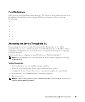
...is complete. 2 When the Console> prompt displays, type enable and press . 3 Configure the device and enter the necessary commands to the Terminal port or via a Telnet connection, ensure that the device has an IP address defined and that the software has ...beginning using CLI commands. If access is via a Telnet connection. For information about configuring an initial IP Address, see "Initial Configuration". Terminal Connection 1 Power on the OpenManage Switch Administrator web page. The session quits. Using Dell OpenManage Switch Administrator 83 All letters or characters can be...
...is complete. 2 When the Console> prompt displays, type enable and press . 3 Configure the device and enter the necessary commands to the Terminal port or via a Telnet connection, ensure that the device has an IP address defined and that the software has ...beginning using CLI commands. If access is via a Telnet connection. For information about configuring an initial IP Address, see "Initial Configuration". Terminal Connection 1 Power on the OpenManage Switch Administrator web page. The session quits. Using Dell OpenManage Switch Administrator 83 All letters or characters can be...
User's Guide (.htm)
Page 101
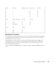
... ---- --- 1 CPU 2 CPU Status -----OK OK Managing Power over Ethernet Power over Ethernet (PoE) provides power to power sources. Powered devices are devices which receive power from the PowerConnect power supplies, for example IP phones. Powered Devices are connected to the PowerConnect device via either all PowerConnect 3424P's 24 FE ports or all PowerConnect 3448P's 48 FE ports. Configuring System Information 101 click System →General...
... ---- --- 1 CPU 2 CPU Status -----OK OK Managing Power over Ethernet Power over Ethernet (PoE) provides power to power sources. Powered devices are devices which receive power from the PowerConnect power supplies, for example IP phones. Powered Devices are connected to the PowerConnect device via either all PowerConnect 3424P's 24 FE ports or all PowerConnect 3448P's 48 FE ports. Configuring System Information 101 click System →General...
User's Guide (.htm)
Page 103
... a fault on PoE. Indicates that the PowerConnect device is receiving power from the power supply. Determines the port priority if the power supply is low. The field default is the default PoE operational status. Assigns the highest power priority level. Indicates the amount of power assigned to the powered device connected to confirm it is currently searching for...
... a fault on PoE. Indicates that the PowerConnect device is receiving power from the power supply. Determines the port priority if the power supply is low. The field default is the default PoE operational status. Assigns the highest power priority level. Indicates the amount of power assigned to the powered device connected to confirm it is currently searching for...


