
User's Guide
Page 9
... devices, such as: • Servers • Hubs • Routers The PowerConnect devices are managed by Dell's OpenManage Switch Administrator. Dell PowerConnect 28xx Systems User Guide 9 The switches are primarily designated for installing, configuring and maintaining the PowerConnect 2808, PowerConnect 2816, PowerConnect 2824, and PowerConnect 2848 Webmanaged Gigabit Ethernet switches. Introduction This User's Guide contains the information needed for the Small Office/Home Office...
... devices, such as: • Servers • Hubs • Routers The PowerConnect devices are managed by Dell's OpenManage Switch Administrator. Dell PowerConnect 28xx Systems User Guide 9 The switches are primarily designated for installing, configuring and maintaining the PowerConnect 2808, PowerConnect 2816, PowerConnect 2824, and PowerConnect 2848 Webmanaged Gigabit Ethernet switches. Introduction This User's Guide contains the information needed for the Small Office/Home Office...
User's Guide
Page 10
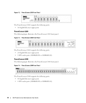
... Ethernet copper ports • 2 SFP combo ports (1000BASE-SX or 1000BASE-LX) PowerConnect 2848 The following figure illustrates the PowerConnect 2824 front panel. Figure 1-2. Figure 1-3. PowerConnect 2848 Front Panel The PowerConnect 2848 supports the following ports: • 48 Gigabit Ethernet copper ports • 4 SFP combo ports (1000BASE-SX or 1000BASE-LX) 10 Dell PowerConnect 28xx Systems User Guide Figure 1-4.
... Ethernet copper ports • 2 SFP combo ports (1000BASE-SX or 1000BASE-LX) PowerConnect 2848 The following figure illustrates the PowerConnect 2824 front panel. Figure 1-2. Figure 1-3. PowerConnect 2848 Front Panel The PowerConnect 2848 supports the following ports: • 48 Gigabit Ethernet copper ports • 4 SFP combo ports (1000BASE-SX or 1000BASE-LX) 10 Dell PowerConnect 28xx Systems User Guide Figure 1-4.

User's Guide
Page 11
... port 1 External console port 2 Features General Features Management Modes The device supports the following table summarizes the PowerConnect models. Dell PowerConnect 28xx Systems User Guide 11 Summary of PowerConnect Models The following modes: • Managed Mode - PowerConnect Models Model PowerConnect 2808 PowerConnect 2816 PowerConnect 2824 PowerConnect 2848 Copper Ports/ RJ-45 Connectors Optical Ports/ GbE 8 built-in 10/100/1000 Base-T ports...
... port 1 External console port 2 Features General Features Management Modes The device supports the following table summarizes the PowerConnect models. Dell PowerConnect 28xx Systems User Guide 11 Summary of PowerConnect Models The following modes: • Managed Mode - PowerConnect Models Model PowerConnect 2808 PowerConnect 2816 PowerConnect 2824 PowerConnect 2848 Copper Ports/ RJ-45 Connectors Optical Ports/ GbE 8 built-in 10/100/1000 Base-T ports...
User's Guide
Page 12
...modes of this facility are detected: • Cable Type and Status • Cable Length • Fault-Distance 12 Dell PowerConnect 28xx Systems User Guide Virtual Cable Testing (VCT) VCT technology provides the mechanism to configure the port speeds advertised. Standard wiring for end stations...Frames Support Jumbo frames are used for server-to 10K bytes. When the system initiates a cable-testing operation, upon explicit user action, the following parameters are reduced transmission overhead and reduced host processing overhead. Jumbo frames are frames with Crossover (MDIX)....
...modes of this facility are detected: • Cable Type and Status • Cable Length • Fault-Distance 12 Dell PowerConnect 28xx Systems User Guide Virtual Cable Testing (VCT) VCT technology provides the mechanism to configure the port speeds advertised. Standard wiring for end stations...Frames Support Jumbo frames are used for server-to 10K bytes. When the system initiates a cable-testing operation, upon explicit user action, the following parameters are reduced transmission overhead and reduced host processing overhead. Jumbo frames are frames with Crossover (MDIX)....

User's Guide
Page 13
... address auto-learning from overflowing. MAC Multicast Support Multicast service is no traffic is received for untagged frames. Dell PowerConnect 28xx Systems User Guide 13 The MAC addresses are forwarded based on a port, and subsequent reducing of unregistered multicast frames. IGMP ...power usage of 16K MAC addresses. MAC Address Supported Features MAC Address Capacity Support The PowerConnect 2808, 2816, 2824 switches support a total of 8K MAC addresses, and the PowerConnect 2848 supports a total of Ethernet connections. Classic bridging (IEEE802.1D) is addressed to...
... address auto-learning from overflowing. MAC Multicast Support Multicast service is no traffic is received for untagged frames. Dell PowerConnect 28xx Systems User Guide 13 The MAC addresses are forwarded based on a port, and subsequent reducing of unregistered multicast frames. IGMP ...power usage of 16K MAC addresses. MAC Address Supported Features MAC Address Capacity Support The PowerConnect 2808, 2816, 2824 switches support a total of 8K MAC addresses, and the PowerConnect 2848 supports a total of Ethernet connections. Classic bridging (IEEE802.1D) is addressed to...
User's Guide
Page 14
... Ethernet cables shorter than 40m. Packets sharing common attributes can specify which Multicast routers are forwarded by the device from physical link disruption 14 Dell PowerConnect 28xx Systems User Guide The benefits of the ingress port and package contents. Port Mirroring The port mirroring mechanism monitors and mirrors network traffic by forwarding copies of...
... Ethernet cables shorter than 40m. Packets sharing common attributes can specify which Multicast routers are forwarded by the device from physical link disruption 14 Dell PowerConnect 28xx Systems User Guide The benefits of the ingress port and package contents. Port Mirroring The port mirroring mechanism monitors and mirrors network traffic by forwarding copies of...

User's Guide
Page 15
... of managing network parameter assignment from a single DHCP server. Fast Link STP can be received from functioning as the root port for the switch Dell PowerConnect 28xx Systems User Guide 15 DHCP Server Dynamic Host Configuration Protocol is an extension to converge. During this delay, and can take 30-60 seconds for each host...
... of managing network parameter assignment from a single DHCP server. Fast Link STP can be received from functioning as the root port for the switch Dell PowerConnect 28xx Systems User Guide 15 DHCP Server Dynamic Host Configuration Protocol is an extension to converge. During this delay, and can take 30-60 seconds for each host...

User's Guide
Page 16
...objects, allowing real-time information to view the results, using the Web management interface in the system. 16 Dell PowerConnect 28xx Systems User Guide The PowerConnect 28xx system can be monitored and configured. Class of Service 802.1p Support The IEEE 802.1p signaling ...browser. TFTP Trivial File Transfer Protocol The PowerConnect 28xx switches support software boot image and software download through which provides network traffic statistics. Class of Service (CoS) Features The PowerConnect 28xx system enables users to define various services for traffic classes ...
...objects, allowing real-time information to view the results, using the Web management interface in the system. 16 Dell PowerConnect 28xx Systems User Guide The PowerConnect 28xx system can be monitored and configured. Class of Service 802.1p Support The IEEE 802.1p signaling ...browser. TFTP Trivial File Transfer Protocol The PowerConnect 28xx switches support software boot image and software download through which provides network traffic statistics. Class of Service (CoS) Features The PowerConnect 28xx system enables users to define various services for traffic classes ...

User's Guide
Page 17
For more information about management modes and transitioning between management modes and to indicate the port status. Dell PowerConnect 28xx Systems User Guide 17 The following figures illustrate the front panels and back panels of the front panel is the Managed Mode LED which...combo 1000 Mbps optical ports can operate at 1000 Mbps, full-duplex mode. Hardware Description Switch Port Configurations PowerConnect 28xx Front and Back Panel Port Description The Dell™ PowerConnect™ 28xx switches use 10/100/1000BASE-T ports on the front panel for connecting to right. These ...
For more information about management modes and transitioning between management modes and to indicate the port status. Dell PowerConnect 28xx Systems User Guide 17 The following figures illustrate the front panels and back panels of the front panel is the Managed Mode LED which...combo 1000 Mbps optical ports can operate at 1000 Mbps, full-duplex mode. Hardware Description Switch Port Configurations PowerConnect 28xx Front and Back Panel Port Description The Dell™ PowerConnect™ 28xx switches use 10/100/1000BASE-T ports on the front panel for connecting to right. These ...

User's Guide
Page 18
Figure 2-2. For more information about management modes and transitioning between management modes and to right. PowerConnect 2816 Back Panel 18 Dell PowerConnect 28xx Systems User Guide On each port there are numbered 1 to indicate the port status. The Power LED on the front panel ...indicates whether the device is used to transition between them, see "Management Modes" on or not. PowerConnect 2816 Front Panel On...
Figure 2-2. For more information about management modes and transitioning between management modes and to right. PowerConnect 2816 Back Panel 18 Dell PowerConnect 28xx Systems User Guide On each port there are numbered 1 to indicate the port status. The Power LED on the front panel ...indicates whether the device is used to transition between them, see "Management Modes" on or not. PowerConnect 2816 Front Panel On...

User's Guide
Page 19
PowerConnect 2824 Front Panel On the front panel there are 24 ports which are logical ports with two physical connections: • An RJ-45 connection for Twisted ... device. The system automatically detects the media used on the front panel is used to transition between them, see "Management Modes" on or not. Dell PowerConnect 28xx Systems User Guide 19 If both RJ-45 and SFP ports are determined by the physical connection used at any one time. A Mode push-button, located on...
PowerConnect 2824 Front Panel On the front panel there are 24 ports which are logical ports with two physical connections: • An RJ-45 connection for Twisted ... device. The system automatically detects the media used on the front panel is used to transition between them, see "Management Modes" on or not. Dell PowerConnect 28xx Systems User Guide 19 If both RJ-45 and SFP ports are determined by the physical connection used at any one time. A Mode push-button, located on...

User's Guide
Page 20
...whether the device is the Managed Mode LED which are 48 ports, which indicates the Ethernet switch operational status and the management mode. PowerConnect 2848 Front Panel On the front panel there are numbered 1 to 48, top down and left to right. NOTE: Only one time...45 connection for Twisted Pair (TP) copper cabling. • An SFP port for fiber connection. A Mode push- 20 Dell PowerConnect 28xx Systems User Guide NOTE: The system can be disabled. PowerConnect 2824 Back Panel Figure 2-7. The four combo ports are present, the SFP port will be the active port, whereas the RJ-...
...whether the device is the Managed Mode LED which are 48 ports, which indicates the Ethernet switch operational status and the management mode. PowerConnect 2848 Front Panel On the front panel there are numbered 1 to 48, top down and left to right. NOTE: Only one time...45 connection for Twisted Pair (TP) copper cabling. • An SFP port for fiber connection. A Mode push- 20 Dell PowerConnect 28xx Systems User Guide NOTE: The system can be disabled. PowerConnect 2824 Back Panel Figure 2-7. The four combo ports are present, the SFP port will be the active port, whereas the RJ-...

User's Guide
Page 21
...PowerConnect 2816 and PowerConnect 2824 switches have the following physical dimensions: • Height - 43.2 mm (1.7008 in.) • Width - 330 mm (12.992 in.) • Depth - 230.50 mm (9.075 in .) LED Definitions The front panel contains LEDs that indicate the status of the PowerConnect 2848 device. Dell PowerConnect 28xx Systems User Guide... mm (1.70 in.) • Width - 440 mm (17.32 in) • Depth - 255 mm (10.04 in .) The PowerConnect 2848 switch has the following figure illustrates the back panel of links, power supply, fan status, and Managed Mode status. button, located on ...
...PowerConnect 2816 and PowerConnect 2824 switches have the following physical dimensions: • Height - 43.2 mm (1.7008 in.) • Width - 330 mm (12.992 in.) • Depth - 230.50 mm (9.075 in .) LED Definitions The front panel contains LEDs that indicate the status of the PowerConnect 2848 device. Dell PowerConnect 28xx Systems User Guide... mm (1.70 in.) • Width - 440 mm (17.32 in) • Depth - 255 mm (10.04 in .) The PowerConnect 2848 switch has the following figure illustrates the back panel of links, power supply, fan status, and Managed Mode status. button, located on ...

User's Guide
Page 22
...duplex mode is turned on page 49. The following figure illustrates the RJ-45 10/100/1000BASE-T LEDs. 22 Dell PowerConnect 28xx Systems User Guide Fan LED Indications LED Color Green Solid Red Solid Description All fans are operating correctly. The following table describes ... Table 2-3. Power LED Indications LED Color Green Solid Off Description The switch is indicated on . Fan LED (2824/2848 only) On the PowerConnect 2824 and PowerConnect 2848 front panel there is a Managed Mode LED monitoring the switch node as well as indicating diagnostic test results....
...duplex mode is turned on page 49. The following figure illustrates the RJ-45 10/100/1000BASE-T LEDs. 22 Dell PowerConnect 28xx Systems User Guide Fan LED Indications LED Color Green Solid Red Solid Description All fans are operating correctly. The following table describes ... Table 2-3. Power LED Indications LED Color Green Solid Off Description The switch is indicated on . Fan LED (2824/2848 only) On the PowerConnect 2824 and PowerConnect 2848 front panel there is a Managed Mode LED monitoring the switch node as well as indicating diagnostic test results....

User's Guide
Page 23
... for resetting the device. For more information about management modes and transitioning between modes, press the button normally. Dell PowerConnect 28xx Systems User Guide 23 The port is established. SFP LED Indications LED Color Description Green Solid Link is transmitting or receiving data ...port is currently transmitting in the following table describes the SFP LED indications. Switch Ventilation Fan The PowerConnect 2848 switch has three fans and the PowerConnect 2824 switch has one fan for system ventilation. The port is linked at 1000 Mbps. Figure 2-9. ...
... for resetting the device. For more information about management modes and transitioning between modes, press the button normally. Dell PowerConnect 28xx Systems User Guide 23 The port is established. SFP LED Indications LED Color Description Green Solid Link is transmitting or receiving data ...port is currently transmitting in the following table describes the SFP LED indications. Switch Ventilation Fan The PowerConnect 2848 switch has three fans and the PowerConnect 2824 switch has one fan for system ventilation. The port is linked at 1000 Mbps. Figure 2-9. ...
User's Guide
Page 24
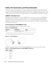
...-T Cable Requirements All Category 5 UTP cables that are only recommendations for 10/100/ 1000BASE-T Ethernet Port Pin No 1 2 3 4 5 Function TxRx 1+ TxRx 1TxRx 2+ TxRx 2TxRx 3+ 24 Dell PowerConnect 28xx Systems User Guide
...-T Cable Requirements All Category 5 UTP cables that are only recommendations for 10/100/ 1000BASE-T Ethernet Port Pin No 1 2 3 4 5 Function TxRx 1+ TxRx 1TxRx 2+ TxRx 2TxRx 3+ 24 Dell PowerConnect 28xx Systems User Guide

User's Guide
Page 25
...system automatically detects the media used at any time. Module definition 1; Receiver ground (common with transmitter ground) Dell PowerConnect 28xx Systems User Guide 25 PowerConnect 2824 switch supports SFP diagnostics. laser output disabled on a combo port, and utilizes this information in the following ... system can be monitored and displayed to a set of signal indication; SFP Ports The PowerConnect 2824 switch supports two SFP transceivers combo ports, and the PowerConnect 2848 switch supports four SFP transceivers combo ports for serial ID. Module definition 2; grounded...
...system automatically detects the media used at any time. Module definition 1; Receiver ground (common with transmitter ground) Dell PowerConnect 28xx Systems User Guide 25 PowerConnect 2824 switch supports SFP diagnostics. laser output disabled on a combo port, and utilizes this information in the following ... system can be monitored and displayed to a set of signal indication; SFP Ports The PowerConnect 2824 switch supports two SFP transceivers combo ports, and the PowerConnect 2848 switch supports four SFP transceivers combo ports for serial ID. Module definition 2; grounded...
User's Guide
Page 26
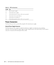
... voltages between 100 and 240 VAC. The AC power connector is powered by using the AC internal power supply. Internal Power Supply Connector The PowerConnect 28xx supports a single internal power supply to provide power for switching operations. SFP Pin Connections Pin No 15 16 17 18 19 20 Use... ground (common with receiver ground) Transmitter non-inverted data in Transmitter inverted data in Transmitter ground (common with receiver ground) Power Connectors The PowerConnect 28xx is located on the back panel of the switch. 26 Dell PowerConnect 28xx Systems User Guide Table 2-8.
... voltages between 100 and 240 VAC. The AC power connector is powered by using the AC internal power supply. Internal Power Supply Connector The PowerConnect 28xx supports a single internal power supply to provide power for switching operations. SFP Pin Connections Pin No 15 16 17 18 19 20 Use... ground (common with receiver ground) Transmitter non-inverted data in Transmitter inverted data in Transmitter ground (common with receiver ground) Power Connectors The PowerConnect 28xx is located on the back panel of the switch. 26 Dell PowerConnect 28xx Systems User Guide Table 2-8.

User's Guide
Page 27
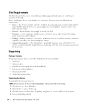
...• Ensure that the cooling vents are properly grounded. • Observe and follow the safety instructions located in the System Information Guide included in the system documentation. Compare this total with the rating limit for the circuit. • Do not install the device... the device does not overload the power circuits, wiring, and over . • Ensure that the device is not restricted. 3 Dell PowerConnect 28xx Systems User Guide 27 Opening or removing covers marked with a triangular symbol with approved equipment. • Allow the device to prevent it may cause ...
...• Ensure that the cooling vents are properly grounded. • Observe and follow the safety instructions located in the System Information Guide included in the system documentation. Compare this total with the rating limit for the circuit. • Do not install the device... the device does not overload the power circuits, wiring, and over . • Ensure that the device is not restricted. 3 Dell PowerConnect 28xx Systems User Guide 27 Opening or removing covers marked with a triangular symbol with approved equipment. • Allow the device to prevent it may cause ...
User's Guide
Page 28
... equipment rack, placed on a tabletop, or mounted on a secure, stable and clean surface. 4 Remove all packing material. 28 Dell PowerConnect 28xx Systems User Guide The ambient device operating temperature range is 0 to 45 °C (32 to 113 °F) at a relative humidity of up ... (for on-shelf installation) • Rack-mount kit for installation • Documentation CD • Product Information Guide Unpacking the Device To unpack the PowerConnect device: NOTE: Before unpacking the device, inspect the packaging and report any evidence of a grounded, easily accessible outlet...
... equipment rack, placed on a tabletop, or mounted on a secure, stable and clean surface. 4 Remove all packing material. 28 Dell PowerConnect 28xx Systems User Guide The ambient device operating temperature range is 0 to 45 °C (32 to 113 °F) at a relative humidity of up ... (for on-shelf installation) • Rack-mount kit for installation • Documentation CD • Product Information Guide Unpacking the Device To unpack the PowerConnect device: NOTE: Before unpacking the device, inspect the packaging and report any evidence of a grounded, easily accessible outlet...


