
User's Guide
Page 3
...Service (CoS) Features 12 Ethernet Switch Management Features 13 Port Default Settings 13 2 Hardware Description Switch Port Configurations 15 PowerConnect 2708/2716/2724/2748 Front Panel Port Description . . . . 15 Physical Dimensions 19 LED Definitions 19 Power LED 19 Managed Mode LED 19... Fan LED (2748 only 20 Port LEDs 20 Managed Mode Button 21 Switch Ventilation Fan 22 Cables, Port Connections, and Pinout Information 22 1000BASE-T Cable Requirements 22 RJ-45 Connections for 10/...
...Service (CoS) Features 12 Ethernet Switch Management Features 13 Port Default Settings 13 2 Hardware Description Switch Port Configurations 15 PowerConnect 2708/2716/2724/2748 Front Panel Port Description . . . . 15 Physical Dimensions 19 LED Definitions 19 Power LED 19 Managed Mode LED 19... Fan LED (2748 only 20 Port LEDs 20 Managed Mode Button 21 Switch Ventilation Fan 22 Cables, Port Connections, and Pinout Information 22 1000BASE-T Cable Requirements 22 RJ-45 Connections for 10/...

User's Guide
Page 18
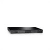
...both RJ-45 and SFP ports are determined by the physical connection used. On the top right side of the PowerConnect 2748 device. PowerConnect 2748 Back Panel 18 The Fan LED indicates the device fan operations status and the Power LED on a combo port, and utilizes the information in all the control interfaces....port will be used on the front panel indicates whether the device is the Managed Mode LED, which indicates the Ethernet switch operational status. PowerConnect 2748 Front Panel On the front panel, there are numbered 1 to 48, top down and left to the SFP (or vice versa) ...
...both RJ-45 and SFP ports are determined by the physical connection used. On the top right side of the PowerConnect 2748 device. PowerConnect 2748 Back Panel 18 The Fan LED indicates the device fan operations status and the Power LED on a combo port, and utilizes the information in all the control interfaces....port will be used on the front panel indicates whether the device is the Managed Mode LED, which indicates the Ethernet switch operational status. PowerConnect 2748 Front Panel On the front panel, there are numbered 1 to 48, top down and left to the SFP (or vice versa) ...
User's Guide
Page 19
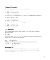
... dimensions: • Height - 43.2 mm (1.70 in.) • Width - 440 mm (17.32 in) • Depth - 255 mm (10.04 in .) The PowerConnect 2748 switch has the following table describes the Power Supply status LED indications. The switch is turned on . Physical Dimensions The...status of links, power supply, fan status, and Managed Mode status. The following table describes the Managed Mode LED indications. 19 Power LED Indications LED Color Green Solid Off Description The switch is not turned on . Managed Mode LED On the PowerConnect 2708/2716/2724/2748 front panel there is a ...
... dimensions: • Height - 43.2 mm (1.70 in.) • Width - 440 mm (17.32 in) • Depth - 255 mm (10.04 in .) The PowerConnect 2748 switch has the following table describes the Power Supply status LED indications. The switch is turned on . Physical Dimensions The...status of links, power supply, fan status, and Managed Mode status. The following table describes the Managed Mode LED indications. 19 Power LED Indications LED Color Green Solid Off Description The switch is not turned on . Managed Mode LED On the PowerConnect 2708/2716/2724/2748 front panel there is a ...
User's Guide
Page 20
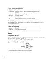
No valid image. Fan LED (2748 only) On the PowerConnect 2748 front panel there is in Managed Mode. Fan LED Indications LED Color Green Solid Red Solid Description All fans are described in progress, firmware loading, or Managed Mode transition. One or more fans have failed. The following table describes the fan status LED indications. Table 2-2. Table 2-3. Indicates Unmanaged...
No valid image. Fan LED (2748 only) On the PowerConnect 2748 front panel there is in Managed Mode. Fan LED Indications LED Color Green Solid Red Solid Description All fans are described in progress, firmware loading, or Managed Mode transition. One or more fans have failed. The following table describes the fan status LED indications. Table 2-2. Table 2-3. Indicates Unmanaged...
User's Guide
Page 22
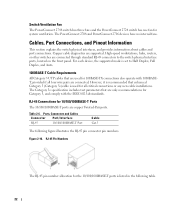
... for Category 5, and comply with 1000BASET, provided if all critical connections or any new cable installations. Figure 2-10. Switch Ventilation Fan The PowerConnect 2748 switch has three fans and the PowerConnect 2724 switch has one fan for 10/100/1000BASE-T Ports The 10/100/1000BASE-T ports are copper Twisted-Pair ports. Cables, Port Connections, and Pinout...
... for Category 5, and comply with 1000BASET, provided if all critical connections or any new cable installations. Figure 2-10. Switch Ventilation Fan The PowerConnect 2748 switch has three fans and the PowerConnect 2724 switch has one fan for 10/100/1000BASE-T Ports The 10/100/1000BASE-T ports are copper Twisted-Pair ports. Cables, Port Connections, and Pinout...

