
User's Guide
Page 17
... the front panel, restores the device's default settings configuration. If both RJ-45 and SFP ports are determined by the physical connection used. PowerConnect 2724 Back Panel 17 NOTE: Only one time. Port features and port controls are present, the SFP port will be the active port,...which are logical ports with two physical connections: • An RJ-45 connection for Twisted Pair (TP) copper cabling • An SFP port for fiber connection. NOTE: The system can be disabled. Figure 2-6. There are LEDs to the SFP (or vice versa) without resetting the device. A Managed ...
... the front panel, restores the device's default settings configuration. If both RJ-45 and SFP ports are determined by the physical connection used. PowerConnect 2724 Back Panel 17 NOTE: Only one time. Port features and port controls are present, the SFP port will be the active port,...which are logical ports with two physical connections: • An RJ-45 connection for Twisted Pair (TP) copper cabling • An SFP port for fiber connection. NOTE: The system can be disabled. Figure 2-6. There are LEDs to the SFP (or vice versa) without resetting the device. A Managed ...

User's Guide
Page 18
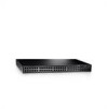
...far right side on a combo port, and utilizes the information in all the control interfaces. PowerConnect 2748 Back Panel 18 Figure 2-7. NOTE: The system can be disabled. The following figure illustrates .... The Fan LED indicates the device fan operations status and the Power LED on or not. PowerConnect 2748 Front Panel On the front panel, there are 48 ports, which are four SFP (Small FormFactor... used at any one time. NOTE: Only one of the two physical connections of the PowerConnect 2748 device. Port features and port controls are LEDs to indicate the port status. If both ...
...far right side on a combo port, and utilizes the information in all the control interfaces. PowerConnect 2748 Back Panel 18 Figure 2-7. NOTE: The system can be disabled. The following figure illustrates .... The Fan LED indicates the device fan operations status and the Power LED on or not. PowerConnect 2748 Front Panel On the front panel, there are 48 ports, which are four SFP (Small FormFactor... used at any one time. NOTE: Only one of the two physical connections of the PowerConnect 2748 device. Port features and port controls are LEDs to indicate the port status. If both ...
User's Guide
Page 23
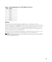
RJ-45 Pin Number Allocation for various fiber-based modules (1000BASE-SX or 1000BASE-LX). The system automatically detects the media used at any time. Table 2-7. PowerConnect 2724 switch supports SFP diagnostics. NOTE: If both RJ-45 and SFP ports are present, the SFP port...switch from the RJ-45 to a set of a combo port can be disabled and ignored. 23 SFP Ports The PowerConnect 2724 switch supports two SFP transceivers combo ports, and the PowerConnect 2748 switch supports four SFP transceivers combo ports for 10/100/ 1000BASE-T Ethernet Port Pin No Function 1 TxRx 1+ 2 ...
RJ-45 Pin Number Allocation for various fiber-based modules (1000BASE-SX or 1000BASE-LX). The system automatically detects the media used at any time. Table 2-7. PowerConnect 2724 switch supports SFP diagnostics. NOTE: If both RJ-45 and SFP ports are present, the SFP port...switch from the RJ-45 to a set of a combo port can be disabled and ignored. 23 SFP Ports The PowerConnect 2724 switch supports two SFP transceivers combo ports, and the PowerConnect 2748 switch supports four SFP transceivers combo ports for 10/100/ 1000BASE-T Ethernet Port Pin No Function 1 TxRx 1+ 2 ...
User's Guide
Page 47
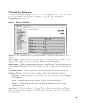
To open the page, click Interface Configuration in the tree view. For example, 100M-Copper or 1000M-Fiber. The port type determines what speed setting options are defined. The current interface type for a port or a LAG, for which interface parameters are available. Active - ...
To open the page, click Interface Configuration in the tree view. For example, 100M-Copper or 1000M-Fiber. The port type determines what speed setting options are defined. The current interface type for a port or a LAG, for which interface parameters are available. Active - ...
User's Guide
Page 63
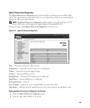
... - Displaying Optical Transceivers Diagnostics Test Results 1 Open the Optical Transceiver Diagnostics page. 2 Select an optic cable interface to PowerConnect 2724 device's SFP ports, which the cable is ready. Output Power - The port on Fiber Optic cables. Internally measured transceiver temperature. The optical transceiver provides access to a set of parameters that the optical...
... - Displaying Optical Transceivers Diagnostics Test Results 1 Open the Optical Transceiver Diagnostics page. 2 Select an optic cable interface to PowerConnect 2724 device's SFP ports, which the cable is ready. Output Power - The port on Fiber Optic cables. Internally measured transceiver temperature. The optical transceiver provides access to a set of parameters that the optical...


