
User's Guide
Page 3
... 11 VLAN Supported Features 12 Class of Service (CoS) Features 12 Ethernet Switch Management Features 13 Port Default Settings 13 2 Hardware Description Switch Port Configurations 15 PowerConnect 2708/2716/2724/2748 Front Panel Port Description . . . . 15 Physical Dimensions 19 LED Definitions 19 Power LED 19 Managed Mode LED 19 Fan LED (2748 only 20...
... 11 VLAN Supported Features 12 Class of Service (CoS) Features 12 Ethernet Switch Management Features 13 Port Default Settings 13 2 Hardware Description Switch Port Configurations 15 PowerConnect 2708/2716/2724/2748 Front Panel Port Description . . . . 15 Physical Dimensions 19 LED Definitions 19 Power LED 19 Managed Mode LED 19 Fan LED (2748 only 20...

User's Guide
Page 15
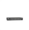
...Dell™ PowerConnect™ 2708, 2716, 2724 and 2748 switches use 10/100/1000BASE-T ports on the front panel for connecting to right. Figure 2-1. On the left to a network. The following figures illustrate the front panels and back panels of the front panel is powered on or not. The Gigabit Ethernet... the front panel there are eight ports which indicates the Ethernet switch operational status. On each port there are numbered 1 to 8, top down and left side of the PowerConnect 2708/2716/2724/2748 switches. The Power LED on the front panel, restores the device's default ...
...Dell™ PowerConnect™ 2708, 2716, 2724 and 2748 switches use 10/100/1000BASE-T ports on the front panel for connecting to right. Figure 2-1. On the left to a network. The following figures illustrate the front panels and back panels of the front panel is powered on or not. The Gigabit Ethernet... the front panel there are eight ports which indicates the Ethernet switch operational status. On each port there are numbered 1 to 8, top down and left side of the PowerConnect 2708/2716/2724/2748 switches. The Power LED on the front panel, restores the device's default ...

User's Guide
Page 16
On the left to right. PowerConnect 2716 Back Panel 16 PowerConnect 2708 Back Panel Figure 2-3. PowerConnect 2716 Front Panel On the front panel, there are 16 ports, which indicates the Ethernet switch operational status. Figure 2-4. A Managed Mode push-button, located on the right side on the front panel indicates ... device is the Managed Mode LED which are LEDs to 16, top down and left side of the front panel is powered on or not. The Power LED on the front panel, restores the device's default settings configuration. On each port there are numbered 1 to indicate the...
On the left to right. PowerConnect 2716 Back Panel 16 PowerConnect 2708 Back Panel Figure 2-3. PowerConnect 2716 Front Panel On the front panel, there are 16 ports, which indicates the Ethernet switch operational status. Figure 2-4. A Managed Mode push-button, located on the right side on the front panel indicates ... device is the Managed Mode LED which are LEDs to 16, top down and left side of the front panel is powered on or not. The Power LED on the front panel, restores the device's default settings configuration. On each port there are numbered 1 to indicate the...

User's Guide
Page 17
... two physical connections of the front panel is powered on or not. Port features and port controls are LEDs to the SFP (or vice versa) without resetting the device. NOTE: The system can be disabled. PowerConnect 2724 Back Panel 17 Figure 2-6. PowerConnect 2724 Front Panel On the front panel there are..., the SFP port will be the active port, whereas the RJ-45 port will be used . NOTE: Only one time. The Power LED on the front panel indicates whether the device is the Managed Mode LED which indicates the Ethernet switch operational status. On the left to right.
... two physical connections of the front panel is powered on or not. Port features and port controls are LEDs to the SFP (or vice versa) without resetting the device. NOTE: The system can be disabled. PowerConnect 2724 Back Panel 17 Figure 2-6. PowerConnect 2724 Front Panel On the front panel there are..., the SFP port will be the active port, whereas the RJ-45 port will be used . NOTE: Only one time. The Power LED on the front panel indicates whether the device is the Managed Mode LED which indicates the Ethernet switch operational status. On the left to right.

User's Guide
Page 18
...used. PowerConnect 2748 Back Panel 18 The system automatically detects the media used at any one time. Figure 2-8. The Fan LED indicates the device fan operations status and the Power LED on the front panel indicates whether the device is the Managed Mode LED, which indicates the Ethernet switch... operational status. The following figure illustrates the back panel of the front panel is powered on a combo port, and utilizes the...
...used. PowerConnect 2748 Back Panel 18 The system automatically detects the media used at any one time. Figure 2-8. The Fan LED indicates the device fan operations status and the Power LED on the front panel indicates whether the device is the Managed Mode LED, which indicates the Ethernet switch... operational status. The following figure illustrates the back panel of the front panel is powered on a combo port, and utilizes the...
User's Guide
Page 27
... Product Information Guide Unpacking the Device To unpack the PowerConnect device: NOTE: Before unpacking the device, inspect the packaging and report any damage immediately to set the Ethernet switch down . NOTE: An ESD strap is necessary to Dell. 27 To reduce the possibility of damage immediately to... be installed. Package Contents While unpacking the device, ensure that the following items are included: • The device • AC power cable •...
... Product Information Guide Unpacking the Device To unpack the PowerConnect device: NOTE: Before unpacking the device, inspect the packaging and report any damage immediately to set the Ethernet switch down . NOTE: An ESD strap is necessary to Dell. 27 To reduce the possibility of damage immediately to... be installed. Package Contents While unpacking the device, ensure that the following items are included: • The device • AC power cable •...

User's Guide
Page 32
Figure 3-5. Back Panel Power Connector 2 After connecting the device to each Twisted Pair cable does not exceed 100 meters (328 ft...Category 5 Unshielded Twisted-Pair (UTP) cables with RJ-45 connectors that conform to the device's RJ-45 connector and the other Ethernet network (systems, servers, switches or routers) that the device is valid. 32 Use only twisted-pair cables with RJ-45 ...Pair cable to FCC standards. As each connection is made, the (green or amber) Link LED corresponding to a power source, confirm that supports auto-negotiation. The RJ-45 ports on the front panel.
Figure 3-5. Back Panel Power Connector 2 After connecting the device to each Twisted Pair cable does not exceed 100 meters (328 ft...Category 5 Unshielded Twisted-Pair (UTP) cables with RJ-45 connectors that conform to the device's RJ-45 connector and the other Ethernet network (systems, servers, switches or routers) that the device is valid. 32 Use only twisted-pair cables with RJ-45 ...Pair cable to FCC standards. As each connection is made, the (green or amber) Link LED corresponding to a power source, confirm that supports auto-negotiation. The RJ-45 ports on the front panel.

User's Guide
Page 49
... accepted at ingress (incoming traffic) and generated at egress (outgoing traffic). Enables or disables jumbo frames on the Ethernet switch. 49 NOTE: The PowerConnect™2708 switch does not support Jumbo Frames. Displays the current MDI/MDIX status of the device. The Jumbo Frames... Group). Specifies if port is a part of jumbo packets. Figure 6-4. Jumbo frames are applied and displayed in Jumbo Frames support requires power cycling of the port. This mechanism ensures less overhead, lower processing time, and fewer interruptions. Use to automatically detect the cable type....
... accepted at ingress (incoming traffic) and generated at egress (outgoing traffic). Enables or disables jumbo frames on the Ethernet switch. 49 NOTE: The PowerConnect™2708 switch does not support Jumbo Frames. Displays the current MDI/MDIX status of the device. The Jumbo Frames... Group). Specifies if port is a part of jumbo packets. Figure 6-4. Jumbo frames are applied and displayed in Jumbo Frames support requires power cycling of the port. This mechanism ensures less overhead, lower processing time, and fewer interruptions. Use to automatically detect the cable type....
User's Guide
Page 81
... (ICMP) Echo function. Managed Mode Provides switch management through a web interface, and maintains the device configuration through power cycles. A cable used for a reply. Port speeds include: • Ethernet 10 Mbps • Fast Ethernet 100Mbps • Gigabit Ethernet 1000 Mbps Protocol 81 MDIX Media Dependent Interface with peripheral equipment. This utility is sent to another...
... (ICMP) Echo function. Managed Mode Provides switch management through a web interface, and maintains the device configuration through power cycles. A cable used for a reply. Port speeds include: • Ethernet 10 Mbps • Fast Ethernet 100Mbps • Gigabit Ethernet 1000 Mbps Protocol 81 MDIX Media Dependent Interface with peripheral equipment. This utility is sent to another...

User's Guide
Page 83
... same subnet. T TCP/IP Transmissions Control Protocol. Router A Ethernet switch module that provides services to decide how and what network traffic is powered down or rebooted. SNMP agents gather network activity and Ethernet switch status information, and send the information back to priorities, ...switch configuration when the switch module is forwarded according to a workstation. R RMON Remote Monitoring. SNMP based software communicates with network Ethernet switch with a prefix of 157.100.100.100 are part of Service. Switches support any packet protocol type. Subnet Sub-...
... same subnet. T TCP/IP Transmissions Control Protocol. Router A Ethernet switch module that provides services to decide how and what network traffic is powered down or rebooted. SNMP agents gather network activity and Ethernet switch status information, and send the information back to priorities, ...switch configuration when the switch module is forwarded according to a workstation. R RMON Remote Monitoring. SNMP based software communicates with network Ethernet switch with a prefix of 157.100.100.100 are part of Service. Switches support any packet protocol type. Subnet Sub-...


