Five-Volt Riser Board Installation
Page 2
...result in this document to refer to avoid the problem. Reproduction in italic type. Dell Computer Corporation disclaims any manner whatsoever without notice. © 2001 Dell Computer Corporation. WARNING: A WARNING indicates a ...used in death or serious bodily injury. These blocks are notes, notices, cautions, and warnings, and they are trademarks of your computer system. Other trademarks and trade names may result in trademarks and trade names other than its own. Information in this text: Dell, the DELL logo, PowerEdge, and PowerApp are used in this document...
...result in this document to refer to avoid the problem. Reproduction in italic type. Dell Computer Corporation disclaims any manner whatsoever without notice. © 2001 Dell Computer Corporation. WARNING: A WARNING indicates a ...used in death or serious bodily injury. These blocks are notes, notices, cautions, and warnings, and they are trademarks of your computer system. Other trademarks and trade names may result in trademarks and trade names other than its own. Information in this text: Dell, the DELL logo, PowerEdge, and PowerApp are used in this document...
Five-Volt Riser Board Installation
Page 3
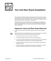
... any 5V PCI cards installed in the Dell™ PowerEdge™ 1550 or PowerApp™ 120 systems. This 5V riser board is mounted high in a single step. Shut down the system and turn off power to the expansion card through the back-panel opening. 5. Release the expansion-card bracket by allowing the user to remove the riser board and its installed expansion card, perform the following steps. Disconnect the power cable from the expansion-card bracket. NOTE...
... any 5V PCI cards installed in the Dell™ PowerEdge™ 1550 or PowerApp™ 120 systems. This 5V riser board is mounted high in a single step. Shut down the system and turn off power to the expansion card through the back-panel opening. 5. Release the expansion-card bracket by allowing the user to remove the riser board and its installed expansion card, perform the following steps. Disconnect the power cable from the expansion-card bracket. NOTE...
Five-Volt Riser Board Installation
Page 4
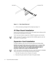
NOTE: Connector PCI1 supports a single short 64-bit, 66-MHz expansion card in connector PCI2 via the 5V riser board. Shut down the system and turn off power to completely remove the system from the rack before performing this connector, a secondary microprocessor cannot occupy the PROCESSOR2 socket. A terminator module must occupy the PROCESSOR2 socket. Disconnect the power cable from the chassis (see Figure 1-1). 5V Riser Board Installation Lower the...
NOTE: Connector PCI1 supports a single short 64-bit, 66-MHz expansion card in connector PCI2 via the 5V riser board. Shut down the system and turn off power to completely remove the system from the rack before performing this connector, a secondary microprocessor cannot occupy the PROCESSOR2 socket. A terminator module must occupy the PROCESSOR2 socket. Disconnect the power cable from the chassis (see Figure 1-1). 5V Riser Board Installation Lower the...
Five-Volt Riser Board Installation
Page 5
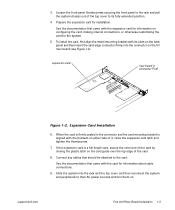
... connector on the card guide over the top edge of it, close the expansion-card latch and tighten the thumbscrew. 7. Connect any cables that came with the expansion card for information on configuring the card, making internal connections, or otherwise customizing the card for installation. See the documentation that should be attached to their AC power sources and turn them on either side of the card. 8. support.dell.com Five-Volt Riser Board Installation...
... connector on the card guide over the top edge of it, close the expansion-card latch and tighten the thumbscrew. 7. Connect any cables that came with the expansion card for information on configuring the card, making internal connections, or otherwise customizing the card for installation. See the documentation that should be attached to their AC power sources and turn them on either side of the card. 8. support.dell.com Five-Volt Riser Board Installation...

PERC 3/DC Cable Installation
Page 1
... updated information for installing the Dell PowerEdge Expandable RAID Controller 3/Dual Channel (PERC 3/DC) in your Dell PowerEdge 1550 or PowerApp 120 system. A00 February 2001 04E580 A00 Cable Description Cable Length Application Short cable PowerEdge 1550 systems and PowerApp 120 systems Long cable All other supported systems To avoid interference with your PowerEdge 1550 or PowerApp 120 system. The PERC 3/DC kit included with your system contains two small computer system interface (SCSI) cables...
... updated information for installing the Dell PowerEdge Expandable RAID Controller 3/Dual Channel (PERC 3/DC) in your Dell PowerEdge 1550 or PowerApp 120 system. A00 February 2001 04E580 A00 Cable Description Cable Length Application Short cable PowerEdge 1550 systems and PowerApp 120 systems Long cable All other supported systems To avoid interference with your PowerEdge 1550 or PowerApp 120 system. The PERC 3/DC kit included with your system contains two small computer system interface (SCSI) cables...

PERC 3/DC Cable Installation
Page 2
...'s Installation and Troubleshooting Guide. Prepare the PERC 3/DC card for installation, and open the system cover. Remove the SCSI backplane board from the system board. e. Reconnect the power cable to the system board, ensuring that the SCSI cable is fully seated. For instructions, see your system's Installation and Troubleshooting Guide. 3. NOTE: Disconnecting the power supply cable will facilitate cable installation in PCI slot 1 by its top corners and insert the card firmly into the PCI slot 2 connector until the card is installed in the chassis. Connect...
...'s Installation and Troubleshooting Guide. Prepare the PERC 3/DC card for installation, and open the system cover. Remove the SCSI backplane board from the system board. e. Reconnect the power cable to the system board, ensuring that the SCSI cable is fully seated. For instructions, see your system's Installation and Troubleshooting Guide. 3. NOTE: Disconnecting the power supply cable will facilitate cable installation in PCI slot 1 by its top corners and insert the card firmly into the PCI slot 2 connector until the card is installed in the chassis. Connect...

PERC 3/DC Cable Installation
Page 3
... sure to configure the card for your system's Installation and Troubleshooting Guide. All rights reserved. For more information on installing expansion cards and redundant array of Dell Computer Corporation is subject to either the entities claiming the marks and names or their products. Information in PCI slot 2, if needed. Trademarks used in this document to refer to change without the written permission of independent disks (RAID) controllers in...
... sure to configure the card for your system's Installation and Troubleshooting Guide. All rights reserved. For more information on installing expansion cards and redundant array of Dell Computer Corporation is subject to either the entities claiming the marks and names or their products. Information in PCI slot 2, if needed. Trademarks used in this document to refer to change without the written permission of independent disks (RAID) controllers in...
Information Update
Page 3
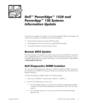
... http:\\support.dell.com. Remove two DIMMs in figure Remote BIOS Update Dell OpenManage™ IT Assistant provides a feature, Remote Flash BIOS, that allows you installed four DIMMs with the same density, the software cannot identify which DIMM is defective. Systems Information Update 1-1 Run the Dell Diagnostics memory test. • For PowerEdge systems, run the memory test from a diagnostics diskette created from the Dell OpenManage Server Assistant CD or from the utility partition. • For PowerApp systems, run the memory test from the Dell PowerApp...
... http:\\support.dell.com. Remove two DIMMs in figure Remote BIOS Update Dell OpenManage™ IT Assistant provides a feature, Remote Flash BIOS, that allows you installed four DIMMs with the same density, the software cannot identify which DIMM is defective. Systems Information Update 1-1 Run the Dell Diagnostics memory test. • For PowerEdge systems, run the memory test from a diagnostics diskette created from the Dell OpenManage Server Assistant CD or from the utility partition. • For PowerApp systems, run the memory test from the Dell PowerApp...
Information Update
Page 4
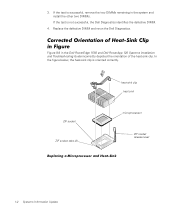
... lever Replacing a Microprocessor and Heat-Sink 1-2 Systems Information Update Replace the defective DIMM and rerun the Dell Diagnostics. Corrected Orientation of the heat-sink clip. In the figure below, the heat-sink clip is not successful, the Dell Diagnostics identifies the defective DIMM. 4. 3. If the test is successful, remove the two DIMMs remaining in the Dell PowerEdge 1550 and Dell PowerApp 120 Systems Installation and Troubleshooting Guide incorrectly depicted the orientation of Heat-Sink...
... lever Replacing a Microprocessor and Heat-Sink 1-2 Systems Information Update Replace the defective DIMM and rerun the Dell Diagnostics. Corrected Orientation of the heat-sink clip. In the figure below, the heat-sink clip is not successful, the Dell Diagnostics identifies the defective DIMM. 4. 3. If the test is successful, remove the two DIMMs remaining in the Dell PowerEdge 1550 and Dell PowerApp 120 Systems Installation and Troubleshooting Guide incorrectly depicted the orientation of Heat-Sink...
Information Update (Removing the Top Cover)
Page 1
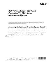
...; 120 Systems Information Update This document updates important information in the figure), and then slowly pull the chassis out to install or remove the system chassis from the rack by yourself. Once the latch has cleared the notch in the top cover, continue to remove the chassis completely, press the spring tabs and pull the chassis out of the chassis rails lock into the cover. www.dell.com support.dell...
...; 120 Systems Information Update This document updates important information in the figure), and then slowly pull the chassis out to install or remove the system chassis from the rack by yourself. Once the latch has cleared the notch in the top cover, continue to remove the chassis completely, press the spring tabs and pull the chassis out of the chassis rails lock into the cover. www.dell.com support.dell...

Information Update (Removing the Top Cover)
Page 2
Other trademarks and trade names may be used in this document to refer to change without notice. © 2000 Dell Computer Corporation. Printed in trademarks and trade names other than its own. Dell Computer Corporation disclaims any proprietary interest in the U.S.A. Trademarks used in this text: Dell, the DELL logo, PowerEdge, and PowerApp are trademarks of Dell Computer Corporation. All rights reserved. Information in this document is subject to either the entities claiming the marks and names or their products.
Other trademarks and trade names may be used in this document to refer to change without notice. © 2000 Dell Computer Corporation. Printed in trademarks and trade names other than its own. Dell Computer Corporation disclaims any proprietary interest in the U.S.A. Trademarks used in this text: Dell, the DELL logo, PowerEdge, and PowerApp are trademarks of Dell Computer Corporation. All rights reserved. Information in this document is subject to either the entities claiming the marks and names or their products.

