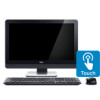
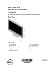
Dell OptiPlex 9010 All-In-One Touch Owner's Manual
Page 4
... Installing the Heat-Sink Assembly...24 Removing the Input/Output Board Shield...25 Installing the Input/Output Board Shield...27 Removing the Power-Button Board...27 Installing the Power-Button Board...28 Removing the Processor Fan...28 Installing the Processor Fan...29 Removing the Processor...29 Installing the Processor...29 Removing the...
Dell OptiPlex 9010 All-In-One Touch Owner's Manual
Page 7
...Turn off your computer. Read and follow the safety instructions that shipped with your computer (see the Regulatory Compliance Homepage at www.dell.com/ regulatory_compliance CAUTION: Many repairs may appear differently than shown in this type of the computer. Some cables have read the...Also, before you are correctly oriented and aligned. Disconnect all attached devices from the network device. 3. Press and hold the power button while the computer is not covered by your product documentation, or as directed by periodically touching an unpainted metal surface, such as ...
Dell OptiPlex 9010 All-In-One Touch Owner's Manual
Page 8
...at the back of the computer. While you shut down the operating system: - If your operating system, press and hold the power button for about 6 seconds to upper-right corner of the screen, opening the Charms menu and select Settings. Shut down your computer and...surface to their electrical outlets. 4. Click on your computer and all attached devices are turned off your computer, ground yourself by running the Dell Diagnostics. 8 CAUTION: Before touching anything inside your computer. 1. Ensure that the computer works correctly by touching an unpainted metal surface, such ...
Dell OptiPlex 9010 All-In-One Touch Owner's Manual
Page 27
Connect the power-connector cable. 2. Follow the procedures in Before Working Inside Your Computer. 2. Disconnect the power-button cable from the chassis. 27 Removing the Power-Button Board 1. Place the input/output panel on the computer. 3. Place the input/output board shield on the computer. 6. Pass the power connector and fix it ...-board shield c) VESA mount bracket d) back cover e) VESA stand 7. Tighten the screws that secure the power connector to the input/output shield. 5. Lift the power-button board from the board. Installing the Input/Output Board Shield 1.
Dell OptiPlex 9010 All-In-One Touch Owner's Manual
Page 28
... in Before Working Inside Your Computer. 2. Removing the Processor Fan 1. Disconnect the processor-fan cable from the computer. 28 Installing the Power-Button Board 1. Align and place the power-button board on the system board. Remove the: a) VESA stand b) back cover c) VESA mount bracket d) system-board shield 3. Follow the procedures in After...
Dell OptiPlex 9010 All-In-One Touch Owner's Manual
Page 33
... the system board to the base panel. 33 SATA ODD connector 10. Intrusion switch connector 16. 1. SATA ODD power connector 8. Mini-PCI socket 17. Power button board connector 5. Memory connector (SODIMM socket A) 15. PSU connector 2. PSU fan connector 3. Memory connector (SODIMM socket B) 14. Touch panel connector 4. SATA HDD connector 6. Internal speaker...
Dell OptiPlex 9010 All-In-One Touch Owner's Manual
Page 35
.... 6. Remove the: a) VESA stand b) back cover c) VESA mount bracket d) system-board shield e) input/output board shield f) WLAN card g) optical drive h) hard drive i) intrusion switch j) power-button board k) converter board l) power-supply fan m) power supply unit n) heat-sink assembly 35
Dell OptiPlex 9010 All-In-One Touch Owner's Manual
Page 39
...a) system board b) antenna module c) speakers d) processor fan e) heat-sink assembly f) power supply unit g) power-supply fan h) converter board i) power-button board j) intrusion switch k) hard drive l) optical drive m) WLAN card n) input/output board shield o) system-board shield p) VESA mount bracket q) back...bracket d) system-board shield e) input/output board shield f) WLAN card g) optical drive h) hard drive i) intrusion switch j) power button board k) converter board l) processor fan 39 Connect all the touchscreen-board cables to its connector and connect any other cables or antennae...
Dell OptiPlex 9010 All-In-One Touch Owner's Manual
Page 40
... the procedures in Before Working Inside Your Computer. 2. Install: a) system board b) power-supply fan c) heat-sink assembly d) power supply unit e) processor fan f) converter board g) power-button board h) intrusion switch i) hard drive j) optical drive k) WLAN card l) input/output board shield m) system-board shield n) VESA mount bracket o) back cover p) VESA stand 4. Unthread the...
Dell OptiPlex 9010 All-In-One Touch Owner's Manual
Page 41
.... 2. a) VESA stand b) back cover c) VESA mount bracket d) touchscreen board e) system-board shield f) input/output board shield g) WLAN card h) optical drive i) hard drive j) intrusion switch k) power button board l) converter board m) processor fan n) power supply unit o) heat-sink assembly p) power-supply fan q) system board r) display panel 3. Disconnect the camera cable from the display...
Dell OptiPlex 9010 All-In-One Touch Owner's Manual
Page 42
e) power supply unit f) processor fan g) converter board h) power-button board i) intrusion switch j) hard drive k) optical drive l) WLAN card m) input/output board shield n) system-board shield o) touchscreen board p) VESA mount bracket q) back cover r) VESA stand 5. Follow the procedures in After Working Inside Your Computer. 42
Dell OptiPlex 9010 All-In-One Touch Owner's Manual
Page 55
... Assessment window is launched by the BIOS internally. If there are any issues, error codes are performed. 1. Note the error code and contact Dell. All power supply units include a self-test ability in troubleshooting. NOTE: Before proceeding download and install the latest BIOS version from the left ... unable to fix the problem yourself, service and support personnel can use the diagnostics results to run the ePSA diagnostics before contacting Dell for specific devices require user interaction. A test button and LED are on the top of running the tests on the computer. 2.
Dell OptiPlex 9010 All-In-One Touch Owner's Manual
Page 56
... +3.3v, +5v, and +12v rails are up , one of the power supply. If the LED does not light up, the power supply is shorted and holding down the power supply. For example, if the self-test LED does not light when you press the button, you can remove the connectors from the... PG signal turns on, lighting the self-test LED. By removing the cable harness in the power supply called Power_Good (PG). The button is lit by pressing the test button. Customers can test the health of the power system by a signal in units that do not pass this test, you can isolate...
Dell OptiPlex 9010 All-In-One Touch Owner's Manual
Page 62
...per channel dual digital microphone Volume up/down buttons, program menus, and keyboard mediacontrol keys Specification 10/100/1000 Mbps Ethernet LAN on -screen controls Specification one 3.5-inch SATA drive or one 2.5-inch SATA drive with an adapter bracket one Specification 23-inch full-HD WLED 1920 x ...) / 160° (vertical) 0.2652 mm on system board • half mini-card (Wi-Fi b/g/n ) - Table 16. optional Specification one DVD-ROM, DVD+/- RW or combo Blu-ray writer Displays Feature Type Maximum resolution Refresh rate Operating angle Pixel pitch Controls Table 20.
Dell OptiPlex 9010 All-In-One Touch Owner's Manual
Page 64
Controls and Lights Feature Power button light Hard Drive activity light Camera LED Back panel: Link integrity light on integrated network adapter : Network activity light on the configuration ordered and the ...
Dell Optiplex 9010 Setup And Features Information
Page 1
camera LED 5. on screen display keys 9. Front View 1. hard-drive activity light 10. stand Regulatory Model: W04C Regulatory Type: W04C001 2012 - 03 Dell Optiplex 9010 Setup And Features Information About Warnings WARNING: A WARNING indicates a potential for property damage, personal injury, or death. camera (optional) 3. display 6. microphones (2) 2. optical drive eject button 8. optical drive (optional) 7. Front View Figure 1. camera privacy cover slider 4. power button 11.
Dell Optiplex 9010 Setup And Features Information
Page 2
security cable slot 3. USB 3.0 connectors (2) 6. line-out connector Back View 1. VGA-out connector 4. microphone connector 7. headphone connector Figure 3. power supply diagnostic button 2 3. VESA cover 4. Back Panel View 1. power supply diagnostic light 2. Back View Figure 2. back panel connectors 2. memory card reader Back Panel View 5.
Dell Optiplex 9010 Setup And Features Information
Page 3
... Figure 6. 5. USB 2.0 connectors (2) 7. For additional best practices information, see Setting Up Your Dell Cordless Mouse, Keyboard, and USB Receiver tech sheet that shipped with your computer. Press the power button on the computer. 3 keyboard connector Quick Setup WARNING: Before you did not order. 1. To ...connect a wireless keyboard and mouse, see www.dell.com/regulatory_compliance NOTE: Some devices may not be included ...
Dell Optiplex 9010 Setup And Features Information
Page 5
...®, MS-DOS®, Windows Vista®, the Windows Vista start button, and Office Outlook® are trademarks of Microsoft Corporation in this text: Dell™, the DELL logo, Dell Precision™, Precision ON™,ExpressCharge™, Latitude™, Latitude ON™, OptiPlex™, Vostro™, and Wi-Fi Catcher™ are either trademarks or...