Dell OptiPlex 9020 AIO Owners Manual
Page 3
......11 Removing the Back Cover...11 Installing the Back Cover...12 Removing the Memory...12 Installing the Memory...13 Removing the VESA Mount Bracket...13 Installing the VESA Mount Bracket...14 Removing the Power and On-Screen Display (OSD) Buttons Board 14 Installing the Power and OSD Buttons Board...15 Removing the System-Board...
......11 Removing the Back Cover...11 Installing the Back Cover...12 Removing the Memory...12 Installing the Memory...13 Removing the VESA Mount Bracket...13 Installing the VESA Mount Bracket...14 Removing the Power and On-Screen Display (OSD) Buttons Board 14 Installing the Power and OSD Buttons Board...15 Removing the System-Board...
Dell OptiPlex 9020 AIO Owners Manual
Page 13
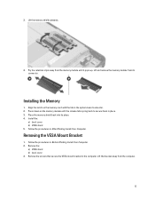
...the memory module until it pops-up. Follow the procedures in the system-board connector. 2. Remove the screws that secure the VESA mount bracket to secure them in Before Working Inside Your Computer. 2. Lift the bracket away from the memory module until the release ...back to the computer. Remove the: a) VESA stand b) back cover 3. Lift the memory shield outwards. 4. Lift and remove the memory module from its place. 4. 3. Install the: a) back cover b) VESA stand 5. Follow the procedures in place. 3. Removing the VESA Mount Bracket 1. Pry the retention clips away from...
...the memory module until it pops-up. Follow the procedures in the system-board connector. 2. Remove the screws that secure the VESA mount bracket to secure them in Before Working Inside Your Computer. 2. Lift the bracket away from the memory module until the release ...back to the computer. Remove the: a) VESA stand b) back cover 3. Lift the memory shield outwards. 4. Lift and remove the memory module from its place. 4. 3. Install the: a) back cover b) VESA stand 5. Follow the procedures in place. 3. Removing the VESA Mount Bracket 1. Pry the retention clips away from...
Dell OptiPlex 9020 AIO Owners Manual
Page 14
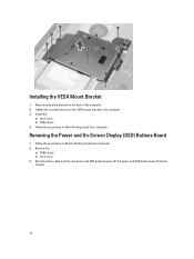
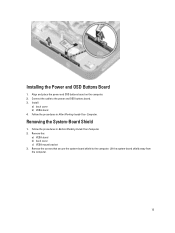
Align and place the bracket on the back of the computer. 2. Follow the procedures in After Working Inside Your Computer. Remove the: a) VESA stand b) back cover 3. Disconnect the cable from the chassis. 14 Lift the power and OSD buttons board from the and power and OSD buttons board. Install the: a) back cover b) VESA stand 4. Tighten the screws that secure the VESA mount bracket to the computer. 3. Removing the Power and On-Screen Display (OSD) Buttons Board 1. Follow the procedures in Before Working Inside Your Computer. 2. Installing the VESA Mount Bracket 1.
Align and place the bracket on the back of the computer. 2. Follow the procedures in After Working Inside Your Computer. Remove the: a) VESA stand b) back cover 3. Disconnect the cable from the chassis. 14 Lift the power and OSD buttons board from the and power and OSD buttons board. Install the: a) back cover b) VESA stand 4. Tighten the screws that secure the VESA mount bracket to the computer. 3. Removing the Power and On-Screen Display (OSD) Buttons Board 1. Follow the procedures in Before Working Inside Your Computer. 2. Installing the VESA Mount Bracket 1.
Dell OptiPlex 9020 AIO Owners Manual
Page 15
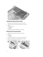
Installing the Power and OSD Buttons Board 1. Removing the System-Board Shield 1. Remove the: a) VESA stand b) back cover c) VESA mount bracket 3. Install: a) back cover b) VESA stand 4. Follow the procedures in Before Working Inside Your Computer. 2. Remove the screws that secure the system-board shield to the power and OSD buttons board. 3. Lift the system-board shield away from the computer. 15 Connect the cable to the computer. Follow the procedures in After Working Inside Your Computer. Align and place the power and OSD buttons board on the computer. 2.
Installing the Power and OSD Buttons Board 1. Removing the System-Board Shield 1. Remove the: a) VESA stand b) back cover c) VESA mount bracket 3. Install: a) back cover b) VESA stand 4. Follow the procedures in Before Working Inside Your Computer. 2. Remove the screws that secure the system-board shield to the power and OSD buttons board. 3. Lift the system-board shield away from the computer. 15 Connect the cable to the computer. Follow the procedures in After Working Inside Your Computer. Align and place the power and OSD buttons board on the computer. 2.
Dell OptiPlex 9020 AIO Owners Manual
Page 16
Install the: a) VESA mount bracket b) back cover c) VESA stand 4. Remove the: a) VESA stand b) back cover 3. Remove the screws that secure the system-board shield to the computer. 5. Tighten the screws that secure the converter board to the ...
Install the: a) VESA mount bracket b) back cover c) VESA stand 4. Remove the: a) VESA stand b) back cover 3. Remove the screws that secure the system-board shield to the computer. 5. Tighten the screws that secure the converter board to the ...
Dell OptiPlex 9020 AIO Owners Manual
Page 19
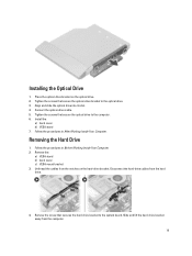
.... 2. Tighten the screws that secure the optical-drive bracket to the system board. Removing the Hard Drive 1. Remove the: a) VESA stand b) back cover c) VESA mount bracket 3. Place the optical-drive bracket on the hard-drive bracket. Connect the optical-drive cable. 5. Unthread the cables from the... After Working Inside Your Computer. Slide and lift the hard-drive bracket away from the hard drive. 4. Install the: a) back cover b) VESA stand 7. Align and slide the optical drive into its slot. 4. Remove the screw that secures the hard-drive bracket to the optical drive....
.... 2. Tighten the screws that secure the optical-drive bracket to the system board. Removing the Hard Drive 1. Remove the: a) VESA stand b) back cover c) VESA mount bracket 3. Place the optical-drive bracket on the hard-drive bracket. Connect the optical-drive cable. 5. Unthread the cables from the... After Working Inside Your Computer. Slide and lift the hard-drive bracket away from the hard drive. 4. Install the: a) back cover b) VESA stand 7. Align and slide the optical drive into its slot. 4. Remove the screw that secures the hard-drive bracket to the optical drive....
Dell OptiPlex 9020 AIO Owners Manual
Page 20
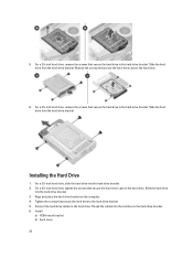
... screws that secure the hard drive to the hard drive. 6. Tighten the screws that secure the hard-drive case to the hard-drive bracket 5. Install: a) VESA mount bracket b) back cover 20 For a 2.5-inch hard drive, remove the screws that secure the hard-drive case to the hard-drive bracket. For a 2.5-inch hard...
... screws that secure the hard drive to the hard drive. 6. Tighten the screws that secure the hard-drive case to the hard-drive bracket 5. Install: a) VESA mount bracket b) back cover 20 For a 2.5-inch hard drive, remove the screws that secure the hard-drive case to the hard-drive bracket. For a 2.5-inch hard...
Dell OptiPlex 9020 AIO Owners Manual
Page 21
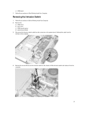
Remove the: a) VESA stand b) back cover c) VESA mount bracket d) system-board shield 3. Follow the procedures in After Working Inside Your Computer. Disconnect the intrusion-switch cable from the connector on the computer. 4. Lift the intrusion switch and remove it from the notches on the system board. Unthread the cable from the computer. 21 c) VESA stand 7. Remove the screws that secure the intrusion switch to the chassis. Follow the procedures in Before Working Inside Your Computer. 2. Removing the Intrusion Switch 1.
Remove the: a) VESA stand b) back cover c) VESA mount bracket d) system-board shield 3. Follow the procedures in After Working Inside Your Computer. Disconnect the intrusion-switch cable from the connector on the computer. 4. Lift the intrusion switch and remove it from the notches on the system board. Unthread the cable from the computer. 21 c) VESA stand 7. Remove the screws that secure the intrusion switch to the chassis. Follow the procedures in Before Working Inside Your Computer. 2. Removing the Intrusion Switch 1.
Dell OptiPlex 9020 AIO Owners Manual
Page 22
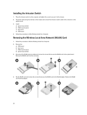
...Place the intrusion switch on the system board. 3. Follow the procedures in Before Working Inside Your Computer. 2. Remove the: a) VESA stand b) back cover c) VESA mount bracket d) system-board shield 3. Remove the WLAN card from the adapter. 22 Remove the WLAN card from the connector. 4. Flip... the screws that secure the WLAN card to the chassis. 2. Installing the Intrusion Switch 1. Install: a) system-board shield b) VESA mount bracket c) back cover d) VESA stand 4. Removing the Wireless Local Area Network (WLAN) Card 1. Thread the cable along the notches on the chassis and connect...
...Place the intrusion switch on the system board. 3. Follow the procedures in Before Working Inside Your Computer. 2. Remove the: a) VESA stand b) back cover c) VESA mount bracket d) system-board shield 3. Remove the WLAN card from the adapter. 22 Remove the WLAN card from the connector. 4. Flip... the screws that secure the WLAN card to the chassis. 2. Installing the Intrusion Switch 1. Install: a) system-board shield b) VESA mount bracket c) back cover d) VESA stand 4. Removing the Wireless Local Area Network (WLAN) Card 1. Thread the cable along the notches on the chassis and connect...
Dell OptiPlex 9020 AIO Owners Manual
Page 23
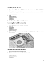
.... 3. Removing the Heat-Sink Assembly 1. sink module to the WLAN adapter 2. Installing the Heat-Sink Assembly 1. Remove the: a) VESA stand b) back cover c) VESA mount bracket d) system-board shield 3. Lift the heat-sink assembly up and remove it from the computer. Remove the screws that secure the...heat- Connect the WLAN cables. 4. Align and place the heat-sink assembly on the computer. 2. Install: a) system-board shield b) VESA mount bracket c) back cover 23 Installing the WLAN Card 1. Tighten the screws to secure the WLAN card to the chassis. Install: a) system-board shield...
.... 3. Removing the Heat-Sink Assembly 1. sink module to the WLAN adapter 2. Installing the Heat-Sink Assembly 1. Remove the: a) VESA stand b) back cover c) VESA mount bracket d) system-board shield 3. Lift the heat-sink assembly up and remove it from the computer. Remove the screws that secure the...heat- Connect the WLAN cables. 4. Align and place the heat-sink assembly on the computer. 2. Install: a) system-board shield b) VESA mount bracket c) back cover 23 Installing the WLAN Card 1. Tighten the screws to secure the WLAN card to the chassis. Install: a) system-board shield...
Dell OptiPlex 9020 AIO Owners Manual
Page 24
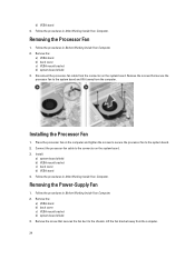
...the computer and tighten the screws to secure the processor fan to the system board. 2. Install: a) system-board shield b) VESA mount bracket c) back cover d) VESA stand 4. Removing the Power-Supply Fan 1. Follow the procedures in Before Working Inside Your Computer. 2. Removing the Processor Fan...Place the processor fan on the system board. 3. Follow the procedures in After Working Inside Your Computer. d) VESA stand 4. Remove the: a) VESA stand b) back cover c) VESA mount bracket d) system-board shield 3. Remove the screws that secures the fan duct to the system board and lift...
...the computer and tighten the screws to secure the processor fan to the system board. 2. Install: a) system-board shield b) VESA mount bracket c) back cover d) VESA stand 4. Removing the Power-Supply Fan 1. Follow the procedures in Before Working Inside Your Computer. 2. Removing the Processor Fan...Place the processor fan on the system board. 3. Follow the procedures in After Working Inside Your Computer. d) VESA stand 4. Remove the: a) VESA stand b) back cover c) VESA mount bracket d) system-board shield 3. Remove the screws that secures the fan duct to the system board and lift...
Dell OptiPlex 9020 AIO Owners Manual
Page 25
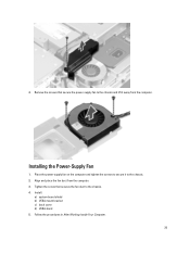
4. Place the power-supply fan on the computer and tighten the screws to secure it away from the computer. 3. Installing the Power-Supply Fan 1. Install: a) system-board shield b) VESA mount bracket c) back cover d) VESA stand 5. Align and place the fan duct from the computer. Remove the screws that secures the fan duct to the chassis. 2. Follow the procedures in After Working Inside Your Computer. 25 Tighten the screw that secure the power-supply fan to the chassis and lift it to the chassis. 4.
4. Place the power-supply fan on the computer and tighten the screws to secure it away from the computer. 3. Installing the Power-Supply Fan 1. Install: a) system-board shield b) VESA mount bracket c) back cover d) VESA stand 5. Align and place the fan duct from the computer. Remove the screws that secures the fan duct to the chassis. 2. Follow the procedures in After Working Inside Your Computer. 25 Tighten the screw that secure the power-supply fan to the chassis and lift it to the chassis. 4.
Dell OptiPlex 9020 AIO Owners Manual
Page 26
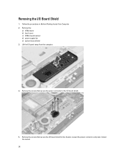
Remove the screws that secure the I/O board shield to the I/O board shield. 5. Loosen the power connector and press it down the socket. 26 Follow the procedures in Before Working Inside Your Computer. 2. Remove the: a) VESA stand b) back cover c) VESA mount bracket d) power supply fan e) system-board shield 3. Lift the I /O Board Shield 1. Removing the I /O panel away from the computer. 4. Remove the screws that secure the power connector to the chassis.
Remove the screws that secure the I/O board shield to the I/O board shield. 5. Loosen the power connector and press it down the socket. 26 Follow the procedures in Before Working Inside Your Computer. 2. Remove the: a) VESA stand b) back cover c) VESA mount bracket d) power supply fan e) system-board shield 3. Lift the I /O Board Shield 1. Removing the I /O panel away from the computer. 4. Remove the screws that secure the power connector to the chassis.
Dell OptiPlex 9020 AIO Owners Manual
Page 28
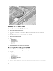
Removing the Power Supply Unit (PSU) 1. Remove the: a) VESA stand b) back cover c) VESA mount bracket d) system-board shield e) input/output (I /O Board Shield 1. Disconnect the power-supply cables from the hooks in the computer. 28 ...Unthread the cable from the system board. Tighten the screws that secure the I /O shield. 5. Install: a) power-supply fan b) system-board shield c) VESA mount bracket d) back cover e) VESA stand 7. Follow the procedures in Before Working Inside Your Computer. 2. Place the I /O board shield on the computer. 6. Follow the procedures in After Working...
Removing the Power Supply Unit (PSU) 1. Remove the: a) VESA stand b) back cover c) VESA mount bracket d) system-board shield e) input/output (I /O Board Shield 1. Disconnect the power-supply cables from the hooks in the computer. 28 ...Unthread the cable from the system board. Tighten the screws that secure the I /O shield. 5. Install: a) power-supply fan b) system-board shield c) VESA mount bracket d) back cover e) VESA stand 7. Follow the procedures in Before Working Inside Your Computer. 2. Place the I /O board shield on the computer. 6. Follow the procedures in After Working...
Dell OptiPlex 9020 AIO Owners Manual
Page 29
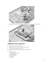
Thread the cable on the system board. 5. Connect the power-supply cables to the connector on the hooks in the computer. 4. Lift the PSU up and remove it from the computer. Place the power supply unit on the computer. 2. Installing the Power Supply Unit 1. Tighten the screws to secure the power supply unit to the chassis. Install: a) power-supply fan b) input/output (I/O) board shield c) system-board shield d) VESA mount bracket e) back cover f) VESA stand 29 4. Remove the screws that secure the PSU to the chassis. 3.
Thread the cable on the system board. 5. Connect the power-supply cables to the connector on the hooks in the computer. 4. Lift the PSU up and remove it from the computer. Place the power supply unit on the computer. 2. Installing the Power Supply Unit 1. Tighten the screws to secure the power supply unit to the chassis. Install: a) power-supply fan b) input/output (I/O) board shield c) system-board shield d) VESA mount bracket e) back cover f) VESA stand 29 4. Remove the screws that secure the PSU to the chassis. 3.
Dell OptiPlex 9020 AIO Owners Manual
Page 30
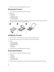
... in After Working Inside Your Computer. Install: a) heat-sink assembly b) system-board shield c) VESA mount bracket d) back cover e) VESA stand 4. Remove the: a) VESA stand b) back cover c) VESA mount bracket d) system-board shield 3. Unthread the cables from the connector on the system board. Follow... the procedures in Before Working Inside Your Computer. 2. Removing the Processor 1. Remove the: a) VESA stand b) back cover c) VESA mount bracket d) system-board shield e) heat-sink assembly 3. Insert the processor into the processor socket. Disconnect the speaker ...
... in After Working Inside Your Computer. Install: a) heat-sink assembly b) system-board shield c) VESA mount bracket d) back cover e) VESA stand 4. Remove the: a) VESA stand b) back cover c) VESA mount bracket d) system-board shield 3. Unthread the cables from the connector on the system board. Follow... the procedures in Before Working Inside Your Computer. 2. Removing the Processor 1. Remove the: a) VESA stand b) back cover c) VESA mount bracket d) system-board shield e) heat-sink assembly 3. Insert the processor into the processor socket. Disconnect the speaker ...
Dell OptiPlex 9020 AIO Owners Manual
Page 31
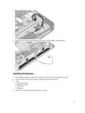
Lift the speakers from the computer. Tighten the screws that secure the speakers to the chassis. Thread the cables on the chassis. Connect the speaker cables to the chassis. 2. Place and align the speakers on the notches. Install: a) system-board shield b) VESA mount bracket c) back cover d) VESA stand 4. Installing the Speakers 1. Follow the procedures in After Working Inside Your Computer. 31 Remove the screws that secure the speaker to the system board. 3. 4.
Lift the speakers from the computer. Tighten the screws that secure the speakers to the chassis. Thread the cables on the chassis. Connect the speaker cables to the chassis. 2. Place and align the speakers on the notches. Install: a) system-board shield b) VESA mount bracket c) back cover d) VESA stand 4. Installing the Speakers 1. Follow the procedures in After Working Inside Your Computer. 31 Remove the screws that secure the speaker to the system board. 3. 4.
Dell OptiPlex 9020 AIO Owners Manual
Page 32
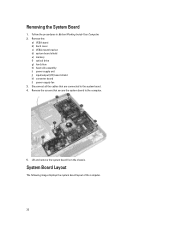
Disconnect all the cables that secure the system board to the system board. 4. Follow the procedures in Before Working Inside Your Computer. 2. Remove the: a) VESA stand b) back cover c) VESA mount bracket d) system-board shield e) memory f) optical drive g) hard drive h) heat-sink assembly i) power supply unit j) input/output (I/O) board shield k) converter board l) power-supply fan...
Disconnect all the cables that secure the system board to the system board. 4. Follow the procedures in Before Working Inside Your Computer. 2. Remove the: a) VESA stand b) back cover c) VESA mount bracket d) system-board shield e) memory f) optical drive g) hard drive h) heat-sink assembly i) power supply unit j) input/output (I/O) board shield k) converter board l) power-supply fan...
Dell OptiPlex 9020 AIO Owners Manual
Page 34
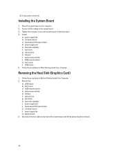
...-sink assembly i) power supply unit j) input/output (I /O) board shield d) power supply unit e) heat-sink assembly f) hard drive g) optical drive h) memory i) system-board shield j) VESA mount bracket k) back cover l) VESA stand 5. Tighten the screws to secure the system board to its back. 34 Disconnect the fan cable connected to the system board and lift...
...-sink assembly i) power supply unit j) input/output (I /O) board shield d) power supply unit e) heat-sink assembly f) hard drive g) optical drive h) memory i) system-board shield j) VESA mount bracket k) back cover l) VESA stand 5. Tighten the screws to secure the system board to its back. 34 Disconnect the fan cable connected to the system board and lift...
Dell OptiPlex 9020 AIO Owners Manual
Page 36
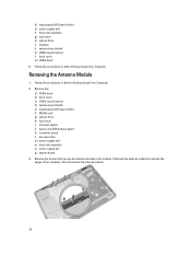
... from around the edges of the computer. Follow the procedures in Before Working Inside Your Computer. 2. Remove the: a) VESA stand b) back cover c) VESA mount bracket d) system-board shield e) input/output (I /O) board shield e) power supply unit f) heat-sink assembly g) hard... drive h) optical drive i) memory j) system-board shield k) VESA mount bracket l) back cover m) VESA stand 5. Removing the Antenna Module 1. d) input/output (I /O) board shield f) WLAN card g) optical drive h) hard drive i) intrusion switch ...
... from around the edges of the computer. Follow the procedures in Before Working Inside Your Computer. 2. Remove the: a) VESA stand b) back cover c) VESA mount bracket d) system-board shield e) input/output (I /O) board shield e) power supply unit f) heat-sink assembly g) hard... drive h) optical drive i) memory j) system-board shield k) VESA mount bracket l) back cover m) VESA stand 5. Removing the Antenna Module 1. d) input/output (I /O) board shield f) WLAN card g) optical drive h) hard drive i) intrusion switch ...


