Dell OptiPlex 9020 AIO Owners Manual
Page 3
... Memory...12 Installing the Memory...13 Removing the VESA Mount Bracket...13 Installing the VESA Mount Bracket...14 Removing the Power and On-Screen Display (OSD) Buttons Board 14 Installing the Power and OSD Buttons Board...15 Removing the System-Board Shield...15 Installing the System-Board Shield...16 Removing the Converter... Area Network (WLAN) Card 22 Installing the WLAN Card...23 Removing the Heat-Sink Assembly...23 Installing the Heat-Sink Assembly...23 Removing the Processor Fan...24 Installing the Processor Fan...24 Removing the Power-Supply Fan...24
... Memory...12 Installing the Memory...13 Removing the VESA Mount Bracket...13 Installing the VESA Mount Bracket...14 Removing the Power and On-Screen Display (OSD) Buttons Board 14 Installing the Power and OSD Buttons Board...15 Removing the System-Board Shield...15 Installing the System-Board Shield...16 Removing the Converter... Area Network (WLAN) Card 22 Installing the WLAN Card...23 Removing the Heat-Sink Assembly...23 Installing the Heat-Sink Assembly...23 Removing the Processor Fan...24 Installing the Processor Fan...24 Removing the Power-Supply Fan...24
Dell OptiPlex 9020 AIO Owners Manual
Page 4
Installing the Power-Supply Fan...25 Removing the I/O Board Shield...26 Installing the I/O Board Shield...28 Removing the Power Supply Unit (PSU)...28 Installing the Power Supply Unit...29 Removing the Processor...30 Installing the Processor...30 Removing the Speakers...30 Installing the Speakers...31 Removing the System Board...32 System Board ... Setup Password...53 Assigning a System Password and Setup Password 54 Deleting or Changing an Existing System and/or Setup Password 54 4 Technical Specifications...57 5 Contacting Dell...63
Installing the Power-Supply Fan...25 Removing the I/O Board Shield...26 Installing the I/O Board Shield...28 Removing the Power Supply Unit (PSU)...28 Installing the Power Supply Unit...29 Removing the Processor...30 Installing the Processor...30 Removing the Speakers...30 Installing the Speakers...31 Removing the System Board...32 System Board ... Setup Password...53 Assigning a System Password and Setup Password 54 Deleting or Changing an Existing System and/or Setup Password 54 4 Technical Specifications...57 5 Contacting Dell...63
Dell OptiPlex 9020 AIO Owners Manual
Page 9
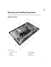
processor fan 5. 2 Removing and Installing Components This section provides detailed information on how to remove or install the components from your computer. Inside View 1. memory module 9 power supply unit (PSU) 2. hard drive 4. heat sink assembly 7. coin-cell battery 6. heat sink 8. camera 3. System Overview Figure 1.
processor fan 5. 2 Removing and Installing Components This section provides detailed information on how to remove or install the components from your computer. Inside View 1. memory module 9 power supply unit (PSU) 2. hard drive 4. heat sink assembly 7. coin-cell battery 6. heat sink 8. camera 3. System Overview Figure 1.
Dell OptiPlex 9020 AIO Owners Manual
Page 10
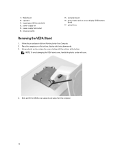
... avoid damaging the VESA stand cover, handle the plastic scribe with the notches at the bottom. Follow the procedures in Before Working Inside Your Computer. 2. power-button and on a flat surface, display side facing downwards. 3. power-supply fan bracket 14. power-supply fan 13. converter board 16. Using a plastic scribe, release the cover starting with care. 4.
... avoid damaging the VESA stand cover, handle the plastic scribe with the notches at the bottom. Follow the procedures in Before Working Inside Your Computer. 2. power-button and on a flat surface, display side facing downwards. 3. power-supply fan bracket 14. power-supply fan 13. converter board 16. Using a plastic scribe, release the cover starting with care. 4.
Dell OptiPlex 9020 AIO Owners Manual
Page 24
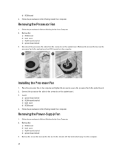
.... Remove the: a) VESA stand b) back cover c) VESA mount bracket d) system-board shield 3. Removing the Processor Fan 1. Remove the screws that secures the fan duct to the system board and lift it away from the connector on the system board. 3. Install: a) system-... d) VESA stand 4. Remove the screw that secure the processor fan to the chassis. Follow the procedures in Before Working Inside Your Computer. 2. Connect the processor-fan cable to the system board. 2. Removing the Power-Supply Fan 1. Installing the Processor Fan 1. Lift the fan bracket away from the computer. 24
.... Remove the: a) VESA stand b) back cover c) VESA mount bracket d) system-board shield 3. Removing the Processor Fan 1. Remove the screws that secures the fan duct to the system board and lift it away from the connector on the system board. 3. Install: a) system-... d) VESA stand 4. Remove the screw that secure the processor fan to the chassis. Follow the procedures in Before Working Inside Your Computer. 2. Connect the processor-fan cable to the system board. 2. Removing the Power-Supply Fan 1. Installing the Processor Fan 1. Lift the fan bracket away from the computer. 24
Dell OptiPlex 9020 AIO Owners Manual
Page 25
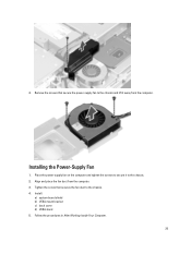
Place the power-supply fan on the computer and tighten the screws to secure it away from the computer. 3. Follow the procedures in After Working Inside Your Computer. 25 Install: a) system-board shield b) VESA mount bracket c) back cover d) VESA stand 5. Installing the Power-Supply Fan 1. Tighten the screw that secure the power-supply fan to the chassis and lift it to the chassis. 4. 4. Align and place the fan duct from the computer. Remove the screws that secures the fan duct to the chassis. 2.
Place the power-supply fan on the computer and tighten the screws to secure it away from the computer. 3. Follow the procedures in After Working Inside Your Computer. 25 Install: a) system-board shield b) VESA mount bracket c) back cover d) VESA stand 5. Installing the Power-Supply Fan 1. Tighten the screw that secure the power-supply fan to the chassis and lift it to the chassis. 4. 4. Align and place the fan duct from the computer. Remove the screws that secures the fan duct to the chassis. 2.
Dell OptiPlex 9020 AIO Owners Manual
Page 26
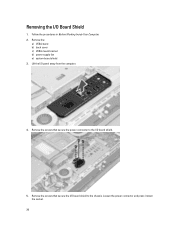
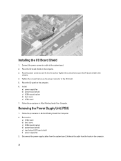
Remove the screws that secure the I/O board shield to the I/O board shield. 5. Removing the I /O panel away from the computer. 4. Lift the I /O Board Shield 1. Remove the: a) VESA stand b) back cover c) VESA mount bracket d) power supply fan e) system-board shield 3. Remove the screws that secure the power connector to the chassis. Follow the procedures in Before Working Inside Your Computer. 2. Loosen the power connector and press it down the socket. 26
Remove the screws that secure the I/O board shield to the I/O board shield. 5. Removing the I /O panel away from the computer. 4. Lift the I /O Board Shield 1. Remove the: a) VESA stand b) back cover c) VESA mount bracket d) power supply fan e) system-board shield 3. Remove the screws that secure the power connector to the chassis. Follow the procedures in Before Working Inside Your Computer. 2. Loosen the power connector and press it down the socket. 26
Dell OptiPlex 9020 AIO Owners Manual
Page 28
Installing the I /O) board shield f) power-supply fan 3. Pass the power connector and fix it to the system board. 2. Tighten the screws that secure the power connector to the I /O board shield to the chassis. 4. Tighten the screws that secure the I /O shield. 5. ... Working Inside Your Computer. 2. Disconnect the power-supply cables from the hooks in the computer. 28 Install: a) power-supply fan b) system-board shield c) VESA mount bracket d) back cover e) VESA stand 7. Removing the Power Supply Unit (PSU) 1. Connect the power-connector cable to the socket. Unthread the...
Installing the I /O) board shield f) power-supply fan 3. Pass the power connector and fix it to the system board. 2. Tighten the screws that secure the power connector to the I /O board shield to the chassis. 4. Tighten the screws that secure the I /O shield. 5. ... Working Inside Your Computer. 2. Disconnect the power-supply cables from the hooks in the computer. 28 Install: a) power-supply fan b) system-board shield c) VESA mount bracket d) back cover e) VESA stand 7. Removing the Power Supply Unit (PSU) 1. Connect the power-connector cable to the socket. Unthread the...
Dell OptiPlex 9020 AIO Owners Manual
Page 29
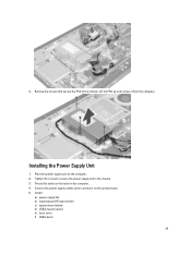
Lift the PSU up and remove it from the computer. Installing the Power Supply Unit 1. Connect the power-supply cables to the connector on the computer. 2. Tighten the screws to secure the power supply unit to the chassis. Remove the screws that secure the PSU to the chassis. 3. Place the power supply unit on the system board. 5. Thread the cable on the hooks in the computer. 4. Install: a) power-supply fan b) input/output (I/O) board shield c) system-board shield d) VESA mount bracket e) back cover f) VESA stand 29 4.
Lift the PSU up and remove it from the computer. Installing the Power Supply Unit 1. Connect the power-supply cables to the connector on the computer. 2. Tighten the screws to secure the power supply unit to the chassis. Remove the screws that secure the PSU to the chassis. 3. Place the power supply unit on the system board. 5. Thread the cable on the hooks in the computer. 4. Install: a) power-supply fan b) input/output (I/O) board shield c) system-board shield d) VESA mount bracket e) back cover f) VESA stand 29 4.
Dell OptiPlex 9020 AIO Owners Manual
Page 32
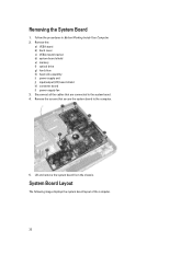
... Computer. 2. Remove the: a) VESA stand b) back cover c) VESA mount bracket d) system-board shield e) memory f) optical drive g) hard drive h) heat-sink assembly i) power supply unit j) input/output (I/O) board shield k) converter board l) power-supply fan 3. Remove the screws that are connected to the computer. 5. Disconnect all the cables that secure the system board to the system board...
... Computer. 2. Remove the: a) VESA stand b) back cover c) VESA mount bracket d) system-board shield e) memory f) optical drive g) hard drive h) heat-sink assembly i) power supply unit j) input/output (I/O) board shield k) converter board l) power-supply fan 3. Remove the screws that are connected to the computer. 5. Disconnect all the cables that secure the system board to the system board...
Dell OptiPlex 9020 AIO Owners Manual
Page 34
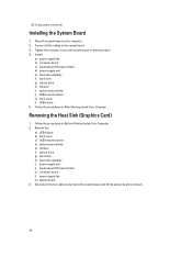
Disconnect the fan cable connected to the system board and lift the system board to the base panel. 4. 20. 8-pin power connector Installing the System Board 1. Tighten the screws to secure the system ... h) heat-sink assembly i) power supply unit j) input/output (I /O) board shield d) power supply unit e) heat-sink assembly f) hard drive g) optical drive h) memory i) system-board shield j) VESA mount bracket k) back cover l) VESA stand 5. Install: a) power-supply fan b) converter board c) input/output (I /O) board shield k) converter board l) power-supply fan m) system board 3. Follow ...
Disconnect the fan cable connected to the system board and lift the system board to the base panel. 4. 20. 8-pin power connector Installing the System Board 1. Tighten the screws to secure the system ... h) heat-sink assembly i) power supply unit j) input/output (I /O) board shield d) power supply unit e) heat-sink assembly f) hard drive g) optical drive h) memory i) system-board shield j) VESA mount bracket k) back cover l) VESA stand 5. Install: a) power-supply fan b) converter board c) input/output (I /O) board shield k) converter board l) power-supply fan m) system board 3. Follow ...
Dell OptiPlex 9020 AIO Owners Manual
Page 35
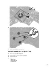
Remove the heat sink from the system board. Install: a) system board b) power-supply fan c) converter board 35 Press and push down the screws that are connected to its position. 3. Press the screws to lock the heat sink to the system board. 5. Place the heat sink on the system board. 2. Installing the Heat Sink (Graphics Card) 1. Connect the fan cable. 4. 4.
Remove the heat sink from the system board. Install: a) system board b) power-supply fan c) converter board 35 Press and push down the screws that are connected to its position. 3. Press the screws to lock the heat sink to the system board. 5. Place the heat sink on the system board. 2. Installing the Heat Sink (Graphics Card) 1. Connect the fan cable. 4. 4.
Dell OptiPlex 9020 AIO Owners Manual
Page 36
... (I /O) board shield f) WLAN card g) optical drive h) hard drive i) intrusion switch j) power and OSD buttons board k) converter board l) processor fan m) power supply unit n) heat-sink assembly o) power-supply fan p) system board 3. Remove the: a) VESA stand b) back cover c) VESA mount bracket d) system-board shield e) input/output (I /O) board shield e) power supply unit f) heat-sink assembly g) hard drive h) optical drive i) memory j) system-board...
... (I /O) board shield f) WLAN card g) optical drive h) hard drive i) intrusion switch j) power and OSD buttons board k) converter board l) processor fan m) power supply unit n) heat-sink assembly o) power-supply fan p) system board 3. Remove the: a) VESA stand b) back cover c) VESA mount bracket d) system-board shield e) input/output (I /O) board shield e) power supply unit f) heat-sink assembly g) hard drive h) optical drive i) memory j) system-board...
Dell OptiPlex 9020 AIO Owners Manual
Page 37
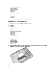
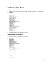
... switch i) hard drive j) optical drive k) WLAN card l) input/output (I /O) board shield f) WLAN card g) optical drive h) hard drive i) intrusion switch j) power and OSD buttons board k) converter board l) power-supply fan m) power supply unit n) heat-sink assembly o) processor fan p) speakers q) antenna module r) system board 37 Removing the Display Panel 1. Remove the: a) VESA stand b) back cover c) VESA mount bracket d) system...
... switch i) hard drive j) optical drive k) WLAN card l) input/output (I /O) board shield f) WLAN card g) optical drive h) hard drive i) intrusion switch j) power and OSD buttons board k) converter board l) power-supply fan m) power supply unit n) heat-sink assembly o) processor fan p) speakers q) antenna module r) system board 37 Removing the Display Panel 1. Remove the: a) VESA stand b) back cover c) VESA mount bracket d) system...

Dell OptiPlex 9020 AIO Owners Manual
Page 40
... in After Working Inside Your Computer. Remove the screws that secure the camera to the chassis. 40 f) power supply unit g) power-supply fan h) converter board i) power and OSD buttons board j) intrusion switch k) hard drive l) optical drive m) WLAN card n) input/output ...(I /O) board shield f) WLAN card g) optical drive h) hard drive i) intrusion switch j) power and OSD buttons board k) converter board l) processor fan m) power supply unit n) heat-sink assembly o) power-supply fan p) system board q) display panel 3. Follow the procedures in Before Working Inside Your Computer. 2....
... in After Working Inside Your Computer. Remove the screws that secure the camera to the chassis. 40 f) power supply unit g) power-supply fan h) converter board i) power and OSD buttons board j) intrusion switch k) hard drive l) optical drive m) WLAN card n) input/output ...(I /O) board shield f) WLAN card g) optical drive h) hard drive i) intrusion switch j) power and OSD buttons board k) converter board l) processor fan m) power supply unit n) heat-sink assembly o) power-supply fan p) system board q) display panel 3. Follow the procedures in Before Working Inside Your Computer. 2....
Dell OptiPlex 9020 AIO Owners Manual
Page 41
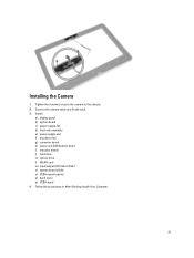
Tighten the screws to secure the camera to the chassis. 2. Follow the procedures in After Working Inside Your Computer. 41 Connect the camera cable and fix the latch. 3. Install: a) display panel b) system board c) power-supply fan d) heat-sink assembly e) power supply unit f) processor fan g) converter board h) power and OSD buttons board i) intrusion switch j) hard drive k) optical drive l) WLAN card m) input/output (I/O) board shield n) system-board shield o) VESA mount bracket p) back cover q) VESA stand 4. Installing the Camera 1.
Tighten the screws to secure the camera to the chassis. 2. Follow the procedures in After Working Inside Your Computer. 41 Connect the camera cable and fix the latch. 3. Install: a) display panel b) system board c) power-supply fan d) heat-sink assembly e) power supply unit f) processor fan g) converter board h) power and OSD buttons board i) intrusion switch j) hard drive k) optical drive l) WLAN card m) input/output (I/O) board shield n) system-board shield o) VESA mount bracket p) back cover q) VESA stand 4. Installing the Camera 1.
Dell OptiPlex 9020 AIO Owners Manual
Page 50
... Disabled - NOTE: This feature does not work if you to disabled. The Smart Connect will not automatically power up. • Every Day - Allows you turn on automatically. NOTE: When enabled, the fan runs at the time you specified above . • Weekdays - This option is disabled by default. The...state) - Controls the speed of the day when you to enable USB devices to AC power supply. This option allows the computer to sleep (S3 state) in the operating system. The system will power up on days selected above at full speed. This option lets you specified above . &#...
... Disabled - NOTE: This feature does not work if you to disabled. The Smart Connect will not automatically power up. • Every Day - Allows you turn on automatically. NOTE: When enabled, the fan runs at the time you specified above . • Weekdays - This option is disabled by default. The...state) - Controls the speed of the day when you to enable USB devices to AC power supply. This option allows the computer to sleep (S3 state) in the operating system. The system will power up on days selected above at full speed. This option lets you specified above . &#...


