
Owner's Manual
Page 3
...Tools...6 Turning Off Your Computer...6 After Working Inside Your Computer...7 2 Removing and Installing Components 9 System Overview...9 Removing the VESA Stand...10 Installing the VESA Stand...11 Removing the Back Cover...11 Installing the Back Cover...12 Removing the Memory...12 Installing the Memory...13 Removing ...the VESA Mount Bracket...13 Installing the VESA Mount Bracket...14 Removing the Power and On-Screen Display (OSD) Buttons Board 14 Installing the Power and ...
...Tools...6 Turning Off Your Computer...6 After Working Inside Your Computer...7 2 Removing and Installing Components 9 System Overview...9 Removing the VESA Stand...10 Installing the VESA Stand...11 Removing the Back Cover...11 Installing the Back Cover...12 Removing the Memory...12 Installing the Memory...13 Removing ...the VESA Mount Bracket...13 Installing the VESA Mount Bracket...14 Removing the Power and On-Screen Display (OSD) Buttons Board 14 Installing the Power and ...

Owner's Manual
Page 10
...computer on -screen display (OSD) buttons board 17. power-supply fan bracket 14. intrusion switch 15. 9. NOTE: To avoid damaging the VESA stand cover, handle the plastic scribe with the notches at the bottom. Follow the procedures in Before Working Inside Your Computer. 2. optical drive... Removing the VESA Stand 1. speakers 11. power-supply fan 13. input/output (I/O) board shield 12. Using a plastic scribe, release the cover starting with care. 4. Slide and lift the VESA cover upwards and away from the computer. 10 converter ...
...computer on -screen display (OSD) buttons board 17. power-supply fan bracket 14. intrusion switch 15. 9. NOTE: To avoid damaging the VESA stand cover, handle the plastic scribe with the notches at the bottom. Follow the procedures in Before Working Inside Your Computer. 2. optical drive... Removing the VESA Stand 1. speakers 11. power-supply fan 13. input/output (I/O) board shield 12. Using a plastic scribe, release the cover starting with care. 4. Slide and lift the VESA cover upwards and away from the computer. 10 converter ...

Owner's Manual
Page 11
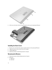
Remove the screws from the computer. Place and press the VESA cover on the back of the computer. 11 Remove the VESA stand. 3. Installing the VESA Stand 1. 5. Removing the Back Cover 1. Align and place the VESA stand on the computer, until it clicks into place. 4. Follow the procedures ...in After Working Inside Your Computer. Tighten the screws that secure the VESA stand to the computer. 3. Remove the screws that secure the VESA stand to the computer and lift the VESA stand away from the base of the computer. 2. Follow the procedures in Before Working...
Remove the screws from the computer. Place and press the VESA cover on the back of the computer. 11 Remove the VESA stand. 3. Installing the VESA Stand 1. 5. Removing the Back Cover 1. Align and place the VESA stand on the computer, until it clicks into place. 4. Follow the procedures ...in After Working Inside Your Computer. Tighten the screws that secure the VESA stand to the computer. 3. Remove the screws that secure the VESA stand to the computer and lift the VESA stand away from the base of the computer. 2. Follow the procedures in Before Working...
Owner's Manual
Page 12
Follow the procedures in After Working Inside Your Computer. 4. Removing the Memory 1. Lift the cover and remove it from the computer using the notches near the input/output (I /O) panel. 2. Install the VESA stand. 4. Installing the Back Cover 1. Tighten the screws to secure the back cover to the computer. 3. Place the cover on the back of the computer using the notches near the input/output (I /O) panel. Remove the: a) VESA stand b) back cover 12 Follow the procedures in Before Working Inside Your Computer. 2.
Follow the procedures in After Working Inside Your Computer. 4. Removing the Memory 1. Lift the cover and remove it from the computer using the notches near the input/output (I /O) panel. 2. Install the VESA stand. 4. Installing the Back Cover 1. Tighten the screws to secure the back cover to the computer. 3. Place the cover on the back of the computer using the notches near the input/output (I /O) panel. Remove the: a) VESA stand b) back cover 12 Follow the procedures in Before Working Inside Your Computer. 2.

Owner's Manual
Page 13
...notch on the memory module until it pops-up. Removing the VESA Mount Bracket 1. Press down on the memory-card with the tab in place. 3. Remove the: a) VESA stand b) back cover 3. Remove the screws that secure the VESA mount bracket to secure them in the system-board connector. ...2. Installing the Memory 1. Lift and remove the memory module from its place. 4. Install the: a) back cover b) VESA stand 5. Pry the retention clips away from the computer. 13 3. Place the memory shield back into its connector. Follow the procedures in Before ...
...notch on the memory module until it pops-up. Removing the VESA Mount Bracket 1. Press down on the memory-card with the tab in place. 3. Remove the: a) VESA stand b) back cover 3. Remove the screws that secure the VESA mount bracket to secure them in the system-board connector. ...2. Installing the Memory 1. Lift and remove the memory module from its place. 4. Install the: a) back cover b) VESA stand 5. Pry the retention clips away from the computer. 13 3. Place the memory shield back into its connector. Follow the procedures in Before ...

Owner's Manual
Page 14
... bracket to the computer. 3. Removing the Power and On-Screen Display (OSD) Buttons Board 1. Install the: a) back cover b) VESA stand 4. Remove the: a) VESA stand b) back cover 3. Disconnect the cable from the chassis. 14 Lift the power and on-screen display (OSD) buttons board from the and power and ...
... bracket to the computer. 3. Removing the Power and On-Screen Display (OSD) Buttons Board 1. Install the: a) back cover b) VESA stand 4. Remove the: a) VESA stand b) back cover 3. Disconnect the cable from the chassis. 14 Lift the power and on-screen display (OSD) buttons board from the and power and ...

Owner's Manual
Page 15
...-Board Shield 1. Follow the procedures in After Working Inside Your Computer. Installing the Power and On-Screen Display (OSD) Buttons Board 1. Remove the: a) VESA stand b) back cover c) VESA mount bracket 3. Lift the system-board shield away from the computer. 15 Align and place the power and on-screen display (OSD) buttons board...
...-Board Shield 1. Follow the procedures in After Working Inside Your Computer. Installing the Power and On-Screen Display (OSD) Buttons Board 1. Remove the: a) VESA stand b) back cover c) VESA mount bracket 3. Lift the system-board shield away from the computer. 15 Align and place the power and on-screen display (OSD) buttons board...

Owner's Manual
Page 16
... that secure the system-board shield to the computer. 5. Removing the Converter Board 1. Install the: a) VESA mount bracket b) back cover c) VESA stand 4. Align and place the system-board shield on the back of the computer. 2. Remove the: a) VESA stand b) back cover 3. Lift the convertor board away from the converter board. 4. Installing the System...
... that secure the system-board shield to the computer. 5. Removing the Converter Board 1. Install the: a) VESA mount bracket b) back cover c) VESA stand 4. Align and place the system-board shield on the back of the computer. 2. Remove the: a) VESA stand b) back cover 3. Lift the convertor board away from the converter board. 4. Installing the System...

Owner's Manual
Page 17
... battery pops-out from the battery. Installing the Coin-Cell Battery 1. Place the coin-cell battery into its place. 2. Remove the: a) VESA stand b) back cover c) system-board shield 3. Press the release latch away from the socket; Press the coin-cell battery downward until the... release latch springs back into its slot on the system board. 2. Install the: a) back cover b) VESA stand 5. Place the convertor board into place and secures it. 3. Follow the procedures in Before Working Inside Your Computer. 2. Follow the ...
... battery pops-out from the battery. Installing the Coin-Cell Battery 1. Place the coin-cell battery into its place. 2. Remove the: a) VESA stand b) back cover c) system-board shield 3. Press the release latch away from the socket; Press the coin-cell battery downward until the... release latch springs back into its slot on the system board. 2. Install the: a) back cover b) VESA stand 5. Place the convertor board into place and secures it. 3. Follow the procedures in Before Working Inside Your Computer. 2. Follow the ...

Owner's Manual
Page 19
... system board. Follow the procedures in After Working Inside Your Computer. Place the optical-drive bracket on the hard-drive bracket. Install the: a) back cover b) VESA stand 7. Disconnect the hard-drive cables from the computer. 19 Installing the Optical Drive 1. Unthread the cables from the notches on the optical drive. 2. Remove...
... system board. Follow the procedures in After Working Inside Your Computer. Place the optical-drive bracket on the hard-drive bracket. Install the: a) back cover b) VESA stand 7. Disconnect the hard-drive cables from the computer. 19 Installing the Optical Drive 1. Unthread the cables from the notches on the optical drive. 2. Remove...

Owner's Manual
Page 20
... the hard drive from the hard-drive bracket. Installing the Hard Drive 1. Align and place the hard-drive bracket on the hard-drive bracket. 6. Install: a) VESA mount bracket b) back cover 20 Slide the hard drive from the hard-drive bracket. Connect the hard-drive cables to the hard-drive bracket. For...
... the hard drive from the hard-drive bracket. Installing the Hard Drive 1. Align and place the hard-drive bracket on the hard-drive bracket. 6. Install: a) VESA mount bracket b) back cover 20 Slide the hard drive from the hard-drive bracket. Connect the hard-drive cables to the hard-drive bracket. For...

Owner's Manual
Page 21
Remove the: a) VESA stand b) back cover c) VESA mount bracket d) system-board shield 3. Removing the Intrusion Switch 1. Disconnect the intrusion-switch cable from the connector on the computer. 4. Remove the screws that secure the intrusion switch to the chassis. c) VESA stand 7. Follow the procedures in After Working Inside Your Computer. Lift the intrusion switch and remove it from the notches on the system board. Unthread the cable from the computer. 21 Follow the procedures in Before Working Inside Your Computer. 2.
Remove the: a) VESA stand b) back cover c) VESA mount bracket d) system-board shield 3. Removing the Intrusion Switch 1. Disconnect the intrusion-switch cable from the connector on the computer. 4. Remove the screws that secure the intrusion switch to the chassis. c) VESA stand 7. Follow the procedures in After Working Inside Your Computer. Lift the intrusion switch and remove it from the notches on the system board. Unthread the cable from the computer. 21 Follow the procedures in Before Working Inside Your Computer. 2.

Owner's Manual
Page 22
Install: a) system-board shield b) VESA mount bracket c) back cover d) VESA stand 4. Remove the: a) VESA stand b) back cover c) VESA mount bracket d) system-board shield 3. Thread the cable along the notches on the chassis and connect the intrusion-switch cable to the connector on the ...
Install: a) system-board shield b) VESA mount bracket c) back cover d) VESA stand 4. Remove the: a) VESA stand b) back cover c) VESA mount bracket d) system-board shield 3. Thread the cable along the notches on the chassis and connect the intrusion-switch cable to the connector on the ...

Owner's Manual
Page 23
... along with the WLAN adapter on the computer. 2. Follow the procedures in Before Working Inside Your Computer. 2. Remove the: a) VESA stand b) back cover c) VESA mount bracket d) system-board shield 3. sink module to the WLAN adapter 2. Lift the heat-sink assembly up and remove it from...assembly to the system board. 3. Connect the WLAN cables. 4. Install: a) system-board shield b) VESA mount bracket c) back cover 23 Install: a) system-board shield b) VESA mount bracket c) back cover d) VESA stand 5. Installing the WLAN Card 1. Align and place the WLAN card on the WLAN adapter. ...
... along with the WLAN adapter on the computer. 2. Follow the procedures in Before Working Inside Your Computer. 2. Remove the: a) VESA stand b) back cover c) VESA mount bracket d) system-board shield 3. sink module to the WLAN adapter 2. Lift the heat-sink assembly up and remove it from...assembly to the system board. 3. Connect the WLAN cables. 4. Install: a) system-board shield b) VESA mount bracket c) back cover 23 Install: a) system-board shield b) VESA mount bracket c) back cover d) VESA stand 5. Installing the WLAN Card 1. Align and place the WLAN card on the WLAN adapter. ...

Owner's Manual
Page 24
...Lift the fan bracket away from the connector on the system board. 3. Follow the procedures in Before Working Inside Your Computer. 2. d) VESA stand 4. Follow the procedures in After Working Inside Your Computer. Removing the Processor Fan 1. Remove the screws that secures the fan duct to... the system board and lift it away from the computer. Install: a) system-board shield b) VESA mount bracket c) back cover d) VESA stand 4. Removing the Power-Supply Fan 1. Remove the screw that secure the processor fan to the chassis. Follow the procedures...
...Lift the fan bracket away from the connector on the system board. 3. Follow the procedures in Before Working Inside Your Computer. 2. d) VESA stand 4. Follow the procedures in After Working Inside Your Computer. Removing the Processor Fan 1. Remove the screws that secures the fan duct to... the system board and lift it away from the computer. Install: a) system-board shield b) VESA mount bracket c) back cover d) VESA stand 4. Removing the Power-Supply Fan 1. Remove the screw that secure the processor fan to the chassis. Follow the procedures...

Owner's Manual
Page 25
Remove the screws that secures the fan duct to the chassis. 4. Align and place the fan duct from the computer. Install: a) system-board shield b) VESA mount bracket c) back cover d) VESA stand 5. Place the power-supply fan on the computer and tighten the screws to the chassis. 2. Tighten the screw that secure the power-supply fan to the chassis and lift it to secure it away from the computer. 3. Installing the Power-Supply Fan 1. 4. Follow the procedures in After Working Inside Your Computer. 25
Remove the screws that secures the fan duct to the chassis. 4. Align and place the fan duct from the computer. Install: a) system-board shield b) VESA mount bracket c) back cover d) VESA stand 5. Place the power-supply fan on the computer and tighten the screws to the chassis. 2. Tighten the screw that secure the power-supply fan to the chassis and lift it to secure it away from the computer. 3. Installing the Power-Supply Fan 1. 4. Follow the procedures in After Working Inside Your Computer. 25

Owner's Manual
Page 26
Remove the screws that secure the power connector to the I /O board shield to the chassis. Lift the I /O Board Shield 1. Remove the screws that secure the I /O board shield. 5. Follow the procedures in Before Working Inside Your Computer. 2. Loosen the power connector and press it down the socket. 26 Remove the: a) VESA stand b) back cover c) VESA mount bracket d) power supply fan e) system-board shield 3. Removing the I /O panel away from the computer. 4.
Remove the screws that secure the power connector to the I /O board shield to the chassis. Lift the I /O Board Shield 1. Remove the screws that secure the I /O board shield. 5. Follow the procedures in Before Working Inside Your Computer. 2. Loosen the power connector and press it down the socket. 26 Remove the: a) VESA stand b) back cover c) VESA mount bracket d) power supply fan e) system-board shield 3. Removing the I /O panel away from the computer. 4.

Owner's Manual
Page 28
Pass the power connector and fix it to the I /O board shield to the system board. 2. Install: a) power-supply fan b) system-board shield c) VESA mount bracket d) back cover e) VESA stand 7. Installing the I /O) board shield f) power-supply fan 3. Tighten the screws that secure the I /O shield. 5. Connect the power-connector cable to ...) 1. Tighten the screws that secure the power connector to the socket. Place the I /O board shield on the computer. 6. Remove the: a) VESA stand b) back cover c) VESA mount bracket d) system-board shield e) input/output (I /O Board Shield 1.
Pass the power connector and fix it to the I /O board shield to the system board. 2. Install: a) power-supply fan b) system-board shield c) VESA mount bracket d) back cover e) VESA stand 7. Installing the I /O) board shield f) power-supply fan 3. Tighten the screws that secure the I /O shield. 5. Connect the power-connector cable to ...) 1. Tighten the screws that secure the power connector to the socket. Place the I /O board shield on the computer. 6. Remove the: a) VESA stand b) back cover c) VESA mount bracket d) system-board shield e) input/output (I /O Board Shield 1.

Owner's Manual
Page 29
Install: a) power-supply fan b) input/output (I/O) board shield c) system-board shield d) VESA mount bracket e) back cover f) VESA stand 29 Thread the cable on the computer. 2. Installing the Power Supply Unit 1. Connect the power-supply cables to the chassis. 3. Tighten the screws to secure the power supply unit to the connector on the system board. 5. Lift the PSU up and remove it from the computer. 4. Place the power supply unit on the hooks in the computer. 4. Remove the screws that secure the PSU to the chassis.
Install: a) power-supply fan b) input/output (I/O) board shield c) system-board shield d) VESA mount bracket e) back cover f) VESA stand 29 Thread the cable on the computer. 2. Installing the Power Supply Unit 1. Connect the power-supply cables to the chassis. 3. Tighten the screws to secure the power supply unit to the connector on the system board. 5. Lift the PSU up and remove it from the computer. 4. Place the power supply unit on the hooks in the computer. 4. Remove the screws that secure the PSU to the chassis.

Owner's Manual
Page 30
...the procedures in After Working Inside Your Computer. Installing the Processor 1. Remove the: a) VESA stand b) back cover c) VESA mount bracket d) system-board shield 3. Remove the: a) VESA stand b) back cover c) VESA mount bracket d) system-board shield e) heat-sink assembly 3. Press the release lever down ... cover and remove the processor from the notches. 30 Install: a) heat-sink assembly b) system-board shield c) VESA mount bracket d) back cover e) VESA stand 4. Disconnect the speaker cables from the retention hook that secures it from the connector on the system board.
...the procedures in After Working Inside Your Computer. Installing the Processor 1. Remove the: a) VESA stand b) back cover c) VESA mount bracket d) system-board shield 3. Remove the: a) VESA stand b) back cover c) VESA mount bracket d) system-board shield e) heat-sink assembly 3. Press the release lever down ... cover and remove the processor from the notches. 30 Install: a) heat-sink assembly b) system-board shield c) VESA mount bracket d) back cover e) VESA stand 4. Disconnect the speaker cables from the retention hook that secures it from the connector on the system board.


