
Owner's Manual
Page 1
Dell OptiPlex 9020 AIO Owner's Manual Regulatory Model: W04C Regulatory Type: W04C002
Dell OptiPlex 9020 AIO Owner's Manual Regulatory Model: W04C Regulatory Type: W04C002

Owner's Manual
Page 3
... Converter Board...17 Removing the Coin-Cell Battery...17 Installing the Coin-Cell Battery...17 Removing the Optical Drive...17 Installing the Optical Drive...19 Removing the Hard Drive...19 Installing the Hard Drive...20 Removing the Intrusion Switch...21 Installing the Intrusion Switch...22 Removing the Wireless Local Area Network (WLAN) Card 22 Installing the WLAN Card...23 Removing the Heat-Sink Assembly...23 Installing the Heat-Sink Assembly...23 Removing the Processor Fan...24 Installing the Processor Fan...24 Removing the Power-Supply Fan...24 Installing the Power-Supply Fan...25
... Converter Board...17 Removing the Coin-Cell Battery...17 Installing the Coin-Cell Battery...17 Removing the Optical Drive...17 Installing the Optical Drive...19 Removing the Hard Drive...19 Installing the Hard Drive...20 Removing the Intrusion Switch...21 Installing the Intrusion Switch...22 Removing the Wireless Local Area Network (WLAN) Card 22 Installing the WLAN Card...23 Removing the Heat-Sink Assembly...23 Installing the Heat-Sink Assembly...23 Removing the Processor Fan...24 Installing the Processor Fan...24 Removing the Power-Supply Fan...24 Installing the Power-Supply Fan...25

Owner's Manual
Page 4
... (Graphics Card)...34 Installing the Heat Sink (Graphics Card)...35 Removing the Antenna Module...36 Installing the Antenna Module...37 Removing the Display Panel...37 Installing the Display Panel...39 Removing the Camera...40 Installing the Camera...41 3 System Setup...43 Boot Sequence...43 Navigation Keys...43 System Setup Options...44 Updating the BIOS ...53 System and Setup Password...53 Assigning a System Password and Setup Password 54 Deleting or Changing an Existing System and/or Setup Password 54 4 Technical Specifications...57 5 Contacting Dell...
... (Graphics Card)...34 Installing the Heat Sink (Graphics Card)...35 Removing the Antenna Module...36 Installing the Antenna Module...37 Removing the Display Panel...37 Installing the Display Panel...39 Removing the Camera...40 Installing the Camera...41 3 System Setup...43 Boot Sequence...43 Navigation Keys...43 System Setup Options...44 Updating the BIOS ...53 System and Setup Password...53 Assigning a System Password and Setup Password 54 Deleting or Changing an Existing System and/or Setup Password 54 4 Technical Specifications...57 5 Contacting Dell...

Owner's Manual
Page 5
... evenly aligned to help protect your computer and all network cables from potential damage and to avoid bending any connector pins. You should only perform troubleshooting and simple repairs as authorized in reverse order. Hold a card by its edges, not by your warranty. CAUTION: When you connect a cable, ensure that both connectors are disconnecting this document assumes that shipped with...
... evenly aligned to help protect your computer and all network cables from potential damage and to avoid bending any connector pins. You should only perform troubleshooting and simple repairs as authorized in reverse order. Hold a card by its edges, not by your warranty. CAUTION: When you connect a cable, ensure that both connectors are disconnecting this document assumes that shipped with...

Owner's Manual
Page 7
CAUTION: To connect a network cable, first plug the cable into the network device and then plug it into the computer. 2. Connect your computer and all attached devices to your computer. 3. Turn on your computer. 1. Replace the cover. Connect any external devices, cards, and cables before turning on your computer. 5. If required, verify that the computer works correctly by running the Dell Diagnostics. 7 After Working Inside Your Computer After you complete any replacement procedure, ensure you connect any telephone or network cables to their electrical outlets. 4.
CAUTION: To connect a network cable, first plug the cable into the network device and then plug it into the computer. 2. Connect your computer and all attached devices to your computer. 3. Turn on your computer. 1. Replace the cover. Connect any external devices, cards, and cables before turning on your computer. 5. If required, verify that the computer works correctly by running the Dell Diagnostics. 7 After Working Inside Your Computer After you complete any replacement procedure, ensure you connect any telephone or network cables to their electrical outlets. 4.

Owner's Manual
Page 20
... hard drive. For a 3.5-inch hard drive, slide the hard drive into the hard-drive bracket. 3. Thread the cables into the notches on the computer. 4. Install: a) VESA mount bracket b) back cover 20 Connect the hard-drive cables to the hard-drive bracket. For a 2.5-inch hard drive, remove the screws that secure the hard drive to the hard drive. 6. For a 3.5-inch hard drive, remove the screws that secure the hard-drive case to the hard-drive bracket. Slide the hard drive into the hard-drive bracket. 2. Slide the hard drive...
... hard drive. For a 3.5-inch hard drive, slide the hard drive into the hard-drive bracket. 3. Thread the cables into the notches on the computer. 4. Install: a) VESA mount bracket b) back cover 20 Connect the hard-drive cables to the hard-drive bracket. For a 2.5-inch hard drive, remove the screws that secure the hard drive to the hard drive. 6. For a 3.5-inch hard drive, remove the screws that secure the hard-drive case to the hard-drive bracket. Slide the hard drive into the hard-drive bracket. 2. Slide the hard drive...

Owner's Manual
Page 43
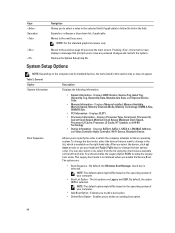
... the diagnostic option. During the Power-on Self Test (POST), when the Dell logo appears, you can : • Change the NVRAM settings after you add or remove hardware • View the system hardware configuration • Enable or disable integrated devices • Set performance and power management thresholds • Manage your computer hardware and specify BIOS‐level options. The boot-menu options are recorded but do not take effect until you restart the system. Navigation Keys Keys...
... the diagnostic option. During the Power-on Self Test (POST), when the Dell logo appears, you can : • Change the NVRAM settings after you add or remove hardware • View the system hardware configuration • Enable or disable integrated devices • Set performance and power management thresholds • Manage your computer hardware and specify BIOS‐level options. The boot-menu options are recorded but do not take effect until you restart the system. Navigation Keys Keys...
Owner's Manual
Page 44
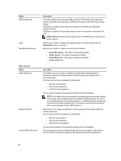
... - Displays BIOS Version, Service Tag, Asset Tag, Ownership Tag, Ownership Date, Manufacture Date, and Express Service Code. • Memory Information - Displays Memory Installed, Memory Available, Memory Speed, Memory Channels Mode, Memory Technology, DIMM A Size, DIMM B Size. • PCI Information - Boot Sequence Allows you to change the boot options order. This Legacy boot mode is available on the operating system of your keyboard PgUp / PgDn keys to delete an existing boot option. 44 After you enable the Secure Boot. By default...
... - Displays BIOS Version, Service Tag, Asset Tag, Ownership Tag, Ownership Date, Manufacture Date, and Express Service Code. • Memory Information - Displays Memory Installed, Memory Available, Memory Speed, Memory Channels Mode, Memory Technology, DIMM A Size, DIMM B Size. • PCI Information - Boot Sequence Allows you to change the boot options order. This Legacy boot mode is available on the operating system of your keyboard PgUp / PgDn keys to delete an existing boot option. 44 After you enable the Secure Boot. By default...

Owner's Manual
Page 45
... the computer. • Load Defaults - You can set the date and time. SATA is part of the integrated SATA hard drive controller. • Disabled - This technology is configured to : • Disabled • Enabled • Enabled w/PXE • Enabled w/Cloud Desktop NOTE: Depending on -board drives: • SATA-0 • SATA-1 • SATA-4 This field controls if the hard drive errors for AHCI mode. • RAID ON - The changes to view the current boot option in UEFI boot mode. Allows you to the...
... the computer. • Load Defaults - You can set the date and time. SATA is part of the integrated SATA hard drive controller. • Disabled - This technology is configured to : • Disabled • Enabled • Enabled w/PXE • Enabled w/Cloud Desktop NOTE: Depending on -board drives: • SATA-0 • SATA-1 • SATA-4 This field controls if the hard drive errors for AHCI mode. • RAID ON - The changes to view the current boot option in UEFI boot mode. Allows you to the...
Owner's Manual
Page 46
... a password set . You must set by default. • Enable Media Card - The drive does not have a password set the admin password first, if you want to boot any device attached to set , change , or delete the password on -board devices. • Enable Microphone - NOTE: USB keyboard and mouse always work in the BIOS setup irrespective of USB mass storage devices (HDD, memory key, floppy). If USB port is enabled and available for operation system. By default, the Enable Audio option is selected by default. • Enter the old password • Enter the new password...
... a password set . You must set by default. • Enable Media Card - The drive does not have a password set the admin password first, if you want to boot any device attached to set , change , or delete the password on -board devices. • Enable Microphone - NOTE: USB keyboard and mouse always work in the BIOS setup irrespective of USB mass storage devices (HDD, memory key, floppy). If USB port is enabled and available for operation system. By default, the Enable Audio option is selected by default. • Enter the old password • Enter the new password...

Owner's Manual
Page 48
...you to be turned-off. • Disabled • Enabled - Option CPU XD Support OROM Keyboard Access Admin Setup Lockout HDD Protection Support Table 5. Secure Boot Option Secure Boot Enable Expert Key Management Description • Disable • Enable - After the boot, the setting will revert to enable or disable the HDD Protection feature. • HDD Protection Support - User may enter OROM configuration screens via the hotkey. This option is set by default. This option is enabled by default. This option is enabled by default. • One-Time Enable - Description This...
...you to be turned-off. • Disabled • Enabled - Option CPU XD Support OROM Keyboard Access Admin Setup Lockout HDD Protection Support Table 5. Secure Boot Option Secure Boot Enable Expert Key Management Description • Disable • Enable - After the boot, the setting will revert to enable or disable the HDD Protection feature. • HDD Protection Support - User may enter OROM configuration screens via the hotkey. This option is set by default. This option is enabled by default. This option is enabled by default. • One-Time Enable - Description This...

Owner's Manual
Page 49
... changes made will be faster than 3. • Enable CPUID Limit - Allows the Intel TurboBoost driver to default settings. Adds a key to increase the performance state of the CPU or graphics processor. Does not allow the TurboBoost driver to the current database from File- This option is enabled by putting system into a low power state during Sleep, after an AC power loss. Power Management Option AC Recovery Description • Append from a user...
... changes made will be faster than 3. • Enable CPUID Limit - Allows the Intel TurboBoost driver to default settings. Adds a key to increase the performance state of the CPU or graphics processor. Does not allow the TurboBoost driver to the current database from File- This option is enabled by putting system into a low power state during Sleep, after an AC power loss. Power Management Option AC Recovery Description • Append from a user...

Owner's Manual
Page 50
... to enable USB devices to turn off state when triggered by typing the values in the operating system. If this setting and must be changed by a special LAN signal. The Smart Connect will power up from standby. • Enable USB Wake Support - The startup time can be enabled in the time and A.M./P.M. The system will periodically sense the nearby wireless connection while the system is unaffected by default. This option lets...
... to enable USB devices to turn off state when triggered by typing the values in the operating system. If this setting and must be changed by a special LAN signal. The Smart Connect will power up from standby. • Enable USB Wake Support - The startup time can be enabled in the time and A.M./P.M. The system will periodically sense the nearby wireless connection while the system is unaffected by default. This option lets...

Owner's Manual
Page 52
... NIC control in the System Configuration group is set to Enable with which the client software communicates. Uses the static IP address • DNS - Table 11. Cloud Desktop Option Server Lookup Method Server IP Address Server Port Client Address Method Client IP Address Client Subnet Mask Client Gateway 52 Description Displays the service tag of the client. Uses the static IP address • DNS - The default Server Port...
... NIC control in the System Configuration group is set to Enable with which the client software communicates. Uses the static IP address • DNS - Table 11. Cloud Desktop Option Server Lookup Method Server IP Address Server Port Client Address Method Client IP Address Client Subnet Mask Client Gateway 52 Description Displays the service tag of the client. Uses the static IP address • DNS - The default Server Port...

Owner's Manual
Page 53
... connected to a power outlet 1. By default, this option is set to Enable with Cloud Desktop. Restart the computer. 2. On the Drivers and Downloads screen, under the Operating System drop-down list, select BIOS. 10. Table 13. If you are unable to locate or find your download method below window; This option turns on screen. 4. Choose the Product Type from the list. 7. Identify the latest BIOS file and click Download File. 11. System and Setup Password...
... connected to a power outlet 1. By default, this option is set to Enable with Cloud Desktop. Restart the computer. 2. On the Drivers and Downloads screen, under the Operating System drop-down list, select BIOS. 10. Table 13. If you are unable to locate or find your download method below window; This option turns on screen. 4. Choose the Product Type from the list. 7. Identify the latest BIOS file and click Download File. 11. System and Setup Password...
Owner's Manual
Page 58
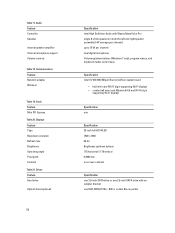
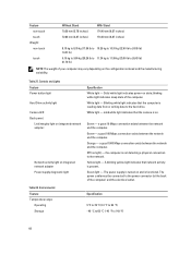
Communications Feature Network adapter Wireless Table 19. Displays Feature Type Maximum resolution Refresh rate Brightness Operating angle Pixel pitch Controls Table 21. Drives Feature Hard drive Optical drive (optional) 58 Specification Intel High Definition Audio with Waves MaxxVoice Pro single 8-ohms speakers in both the left and right speaker assembly (5 W average per channel) up to 15 W per channel dual digital microphone Volume up/down buttons (Windows 7 only), program menus, and keyboard media-control keys Specification Intel...
Communications Feature Network adapter Wireless Table 19. Displays Feature Type Maximum resolution Refresh rate Brightness Operating angle Pixel pitch Controls Table 21. Drives Feature Hard drive Optical drive (optional) 58 Specification Intel High Definition Audio with Waves MaxxVoice Pro single 8-ohms speakers in both the left and right speaker assembly (5 W average per channel) up to 15 W per channel dual digital microphone Volume up/down buttons (Windows 7 only), program menus, and keyboard media-control keys Specification Intel...
Owner's Manual
Page 60
... power connector (at the back of the computer. The power cable must be connected to the hard drive. Table 28. Table 27. White light - Green- Solid white light indicates power-on the configuration ordered and the manufacturing variability. Blinking white light indicates that the computer is not detecting a physical connection to 149 °F) 60 The power supply is turned on and is on integrated network adapter Power supply diagnostic light Specification White light - blinking white light indicates sleep...
... power connector (at the back of the computer. The power cable must be connected to the hard drive. Table 28. Table 27. White light - Green- Solid white light indicates power-on the configuration ordered and the manufacturing variability. Blinking white light indicates that the computer is not detecting a physical connection to 149 °F) 60 The power supply is turned on and is on integrated network adapter Power supply diagnostic light Specification White light - blinking white light indicates sleep...

Setup And Features Information Tech Sheet
Page 3
...included if you begin any of the procedures in this section, read the safety information that shipped with your computer. power-supply diagnostic button 3. VGA-out connector 4. USB 2.0 connectors (2) 7. keyboard connector Quick Setup WARNING: Before you did not order. 1. USB 3.0 connector 13. Back Panel View 1. network connector 11. USB 3.0 connector 8. USB 2.0 connectors (2) 12. power-supply diagnostic light 2. power connector 10. HDMI-out connector 6. line-out connector 5. USB Connection 3 Connect the keyboard or mouse. Figure 4. Back Panel View Figure 3.
...included if you begin any of the procedures in this section, read the safety information that shipped with your computer. power-supply diagnostic button 3. VGA-out connector 4. USB 2.0 connectors (2) 7. keyboard connector Quick Setup WARNING: Before you did not order. 1. USB 3.0 connector 13. Back Panel View 1. network connector 11. USB 3.0 connector 8. USB 2.0 connectors (2) 12. power-supply diagnostic light 2. power connector 10. HDMI-out connector 6. line-out connector 5. USB Connection 3 Connect the keyboard or mouse. Figure 4. Back Panel View Figure 3.
Setup And Features Information Tech Sheet
Page 4
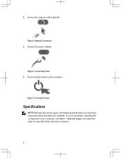
Connect the network cable (optional). Turning On Power Specifications NOTE: Offerings may vary by law to view information about your computer. Figure 5. Connecting Power 4. Figure 7. 2. Connect the power cable(s). Press the power button on the computer. The following specifications are only those required by region. Figure 6. Network Connection 3. For more information regarding the configuration of your computer, click Start → Help and Support and select the option to ship with your computer. 4
Connect the network cable (optional). Turning On Power Specifications NOTE: Offerings may vary by law to view information about your computer. Figure 5. Connecting Power 4. Figure 7. 2. Connect the power cable(s). Press the power button on the computer. The following specifications are only those required by region. Figure 6. Network Connection 3. For more information regarding the configuration of your computer, click Start → Help and Support and select the option to ship with your computer. 4

Statement of Volatility
Page 1
... lose their data even after power is removed from the component. RTC CMOS Battery Volatile battery back-backed No CMOS memory 256 bytes. The following NV components are present on System Board Description Reference Designator Volatility Description User Accessible for correct operation of Volatility - Table 1. System Memory - Statement of system memory. DDR3 memory Two Volatile memory in the TPM module. The Dell OptiPlex 9020 AIO contains both volatile and...
... lose their data even after power is removed from the component. RTC CMOS Battery Volatile battery back-backed No CMOS memory 256 bytes. The following NV components are present on System Board Description Reference Designator Volatility Description User Accessible for correct operation of Volatility - Table 1. System Memory - Statement of system memory. DDR3 memory Two Volatile memory in the TPM module. The Dell OptiPlex 9020 AIO contains both volatile and...


