Dell OptiPlex 9020 AIO Support Question
Dell OptiPlex 9020 AIO Support Question
Find answers below for this question about Dell OptiPlex 9020 AIO.Need a Dell OptiPlex 9020 AIO manual? We have 3 online manuals for this item!
Question posted by oscarluk on November 24th, 2015
Front Panel Phone Jack No Output
optiplex 9020,no output at the front panel phone jack,but the rear panel phone jack is normal
Current Answers
Answer #1: Posted by TommyKervz on November 24th, 2015 2:44 AM
TommyKervz

Member since:
January 10th, 2013 Points: 17,776,813

Member since:
January 10th, 2013 Points: 17,776,813
The card jack might be defected or not properly plugged from the motherboard.
Related Dell OptiPlex 9020 AIO Manual Pages
Owner's Manual - Page 1

Dell OptiPlex 9020 AIO Owner's Manual
Regulatory Model: W04C Regulatory Type: W04C002
Owner's Manual - Page 4

... (Graphics Card)...34 Installing the Heat Sink (Graphics Card)...35 Removing the Antenna Module...36 Installing the Antenna Module...37 Removing the Display Panel...37 Installing the Display Panel...39 Removing the Camera...40 Installing the Camera...41
3 System Setup...43
Boot Sequence...43 Navigation Keys...43 System Setup Options...44 Updating...
Owner's Manual - Page 10

power-supply fan 13. optical drive
Removing the VESA Stand
1. input/output (I/O) board shield 12. power-supply fan bracket 14. Follow the procedures in Before Working Inside Your Computer. 2. NOTE: To avoid damaging the VESA stand cover, ...
Owner's Manual - Page 12
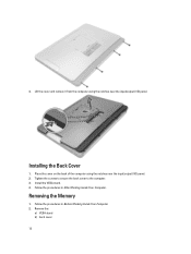
... Inside Your Computer. Remove the:
a) VESA stand b) back cover 12 Lift the cover and remove it from the computer using the notches near the input/output (I /O) panel. 2.
Place the cover on the back of the computer using the notches near the input...
Owner's Manual - Page 26

Remove the screws that secure the I /O board shield.
5. Removing the I /O panel away from the computer.
4. Remove the screws that secure the power connector to the I /O board shield to the chassis. Remove the:
a) VESA stand b) back cover c) ...
Owner's Manual - Page 27

6. Disconnect the power-connector cable from the computer. 7. Flip the input/output (I/O) board shield and remove it from the system board.
27
Owner's Manual - Page 28

Place the I /O panel on the computer.
3. Tighten the screws that secure the I /O shield.
5. Connect... bracket d) back cover e) VESA stand
7. Remove the: a) VESA stand b) back cover c) VESA mount bracket d) system-board shield e) input/output (I /O Board Shield
1. Removing the Power Supply Unit (PSU)
1. Follow the procedures in the computer.
28 Unthread the cable from the system ...
Owner's Manual - Page 29

Install:
a) power-supply fan b) input/output (I/O) board shield c) system-board shield d) VESA mount bracket e) back cover f) VESA stand
29 Remove the screws that secure the PSU to the chassis. 3. Tighten the ...
Owner's Manual - Page 32

... Board
1. Remove the:
a) VESA stand b) back cover c) VESA mount bracket d) system-board shield e) memory f) optical drive g) hard drive h) heat-sink assembly i) power supply unit j) input/output (I/O) board shield k) converter board l) power-supply fan 3. Remove the screws that are connected to the computer.
5. Lift and remove the system board from the chassis.
Owner's Manual - Page 34

...board shield e) memory f) optical drive g) hard drive h) heat-sink assembly i) power supply unit j) input/output (I /O) board shield d) power supply unit e) heat-sink assembly f) hard drive g) optical drive h) ... mount bracket k) back cover l) VESA stand 5. Connect all the cables to the base panel. 4. Removing the Heat Sink (Graphics Card)
1.
Follow the procedures in Before Working Inside...
Owner's Manual - Page 36

d) input/output (I /O) board shield f) WLAN card g) optical drive h) hard drive i) intrusion switch j) power and on-...secure the antenna module to the chassis.
Remove the:
a) VESA stand b) back cover c) VESA mount bracket d) system-board shield e) input/output (I /O) board shield e) power supply unit f) heat-sink assembly g) hard drive h) optical drive i) memory j) system-board shield k) VESA ...
Owner's Manual - Page 37

Removing the Display Panel
1. Follow the procedures in After Working Inside Your Computer. Follow the ...f) converter board g) power and on-screen display (OSD) buttons board h) intrusion switch i) hard drive j) optical drive k) WLAN card l) input/output (I /O) board shield f) WLAN card g) optical drive h) hard drive i) intrusion switch j) power and on the chassis.
2. Installing the Antenna...
Owner's Manual - Page 38

... LVDS cable from the chassis.
5. Remove the screws that secure the base panel to the chassis. NOTE: These instructions are valid only for non-touch computers. Lift the base panel from the display panel. Lift the display panel from the chassis.
38 For touch computers, the display panel should be disassembled in a clean-room environment. 3.
Owner's Manual - Page 39

... to the chassis. 5. Install:
a) system board b) antenna module c) speakers d) processor fan e) heat-sink assembly
39
Installing the Display Panel
1. Tighten the screws to secure the base panel to the display panel. 6. Tighten the screws to secure the display bracket to the display panel. Remove the screws that secure the display bracket to the display...
Owner's Manual - Page 40
...:
a) VESA stand b) back cover c) VESA mount bracket d) system-board shield e) input/output (I /O) board shield o) system-board shield p) VESA mount bracket q) back cover r) VESA...-screen display (OSD) buttons board j) intrusion switch k) hard drive l) optical drive m) WLAN card n) input/output (I /O) board shield f) WLAN card g) optical drive h) hard drive i) intrusion switch j) power and on-screen...
Owner's Manual - Page 41

... Inside Your Computer.
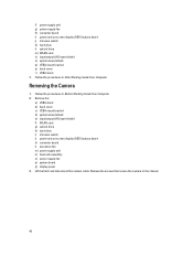
41 Installing the Camera
1. Install:
a) display panel b) system board c) power-supply fan d) heat-sink assembly e) power supply unit f) processor fan g) converter board h) power and on-screen display (OSD) buttons board i) intrusion switch j) hard drive k) optical drive l) WLAN card m) input/output (I/O) board shield n) system-board shield o) VESA mount bracket p) back...
Setup And Features Information Tech Sheet - Page 1

Front View
Figure 1.
microphone (left) 2. Dell OptiPlex 9020 AlO
Setup And Features Information
About Warnings
WARNING: A WARNING indicates a potential for property damage, personal injury, or death. camera (optional)
3. Front View
1. camera tilt wheel (touch screen) / camera slide bar (non-touch screen)
Regulatory Model: W04C Regulatory Type: W04C002
2013 - 02
Setup And Features Information Tech Sheet - Page 2

...microphone (right)
NOTE:
The location of microphone varies in the non-touch version. 6. stand
Figure 2. security cable slot 3. microphone connector 7. display 7. Back View 1. back panel connectors 2. optical drive (optional)
Back View
8. VESA cover 4. headphone connector optical drive eject button 9. hard-drive activity light 11. USB 3.0 connectors (2) 6. 4. power button...
Setup And Features Information Tech Sheet - Page 3

..., read the safety information that shipped with your computer. line-out connector 5. HDMI-out connector 6. power connector 10. USB 3.0 connector
8. USB 3.0 connector 13. Back Panel View
Figure 3. power-supply diagnostic button 3. USB 2.0 connectors (2) 12. mouse connector 9.
USB Connection 3 Figure 4. VGA-out connector 4. USB 2.0 connectors (2) 7. keyboard connector
Quick Setup...
Statement of Volatility - Page 1

... from the component. SMSC5555
Panel EDID U29
Non-volatile memory, 1024
No
N/A
& setting in the TPM module. System memory
XMM1,3
size will depend on -chip RAM. June 2013 Stores
CMOS information. Statement of data and tells you how to two modules must be
connectors: populated. The Dell OptiPlex 9020 AIO contains both volatile and...
Similar Questions

What Motherboard And Cpu Will Be The Best Fit For The Dell Desktop Optiplex 740
(Posted by rmalone3108 2 years ago)

Dell Desktop Optiplex 360 How To Connect Two Monitors
(Posted by mekesdaka 10 years ago)

Dell Desktop Optiplex 330 Does Not Startup Internal P2 Connection Has Defect
(Posted by xydgari 10 years ago)

Head Phone Jack
My jack for headphones stopped working after I installed AGV and had upgraded my dell windows 7
My jack for headphones stopped working after I installed AGV and had upgraded my dell windows 7
(Posted by garylyndhurst 11 years ago)

Need Info About Motherboard Manuufacturer On Motherboard.
i want to replace the motherboard on current "Dell Desktop Optiplex Model GX 260 DHS series. i don't...
i want to replace the motherboard on current "Dell Desktop Optiplex Model GX 260 DHS series. i don't...
(Posted by Terry51chevy 11 years ago)