Owner's Manual
Page 4
Installing the Power Switch...24 Removing the Hard Drive...24 Installing the Hard Drive...26 Removing the System Board...26 System Board Components...30 Installing the System Board...31 Removing the Display Bracket...31 Installing the Display Bracket...34 Removing the Camera...35 Installing the Camera...35 Removing the Serial Port...36 Installing the Serial Port...37 3 System Setup...39...-Boot System Assessment (ePSA) Diagnostics 51 5 Troubleshooting Your Computer 53 Diagnostic Power LED Codes...53 Beep Codes...54 Error Messages...54 6 Technical Specifications...57 7 Contacting Dell...63
Installing the Power Switch...24 Removing the Hard Drive...24 Installing the Hard Drive...26 Removing the System Board...26 System Board Components...30 Installing the System Board...31 Removing the Display Bracket...31 Installing the Display Bracket...34 Removing the Camera...35 Installing the Camera...35 Removing the Serial Port...36 Installing the Serial Port...37 3 System Setup...39...-Boot System Assessment (ePSA) Diagnostics 51 5 Troubleshooting Your Computer 53 Diagnostic Power LED Codes...53 Beep Codes...54 Error Messages...54 6 Technical Specifications...57 7 Contacting Dell...63
Owner's Manual
Page 10
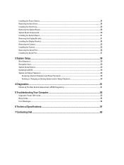
...in Before Working Inside Your Computer. 2. Remove the stand cover. 3. hard drive 12. power switch 14. Follow the procedures in After Working Inside Your Computer. 5. speaker 10. communication port 13. Remove the screws that secure the VESA stand to the computer and remove the VESA stand from the computer. Place... board 8. Installing the Stand Cover 1. memory 7. coin-cell battery 9. Follow the procedures in to release the stand cover and remove it to secure it from the computer. 10 Removing the VESA Stand 1. chassis Removing the Stand Cover 1. heat sink 6.
...in Before Working Inside Your Computer. 2. Remove the stand cover. 3. hard drive 12. power switch 14. Follow the procedures in After Working Inside Your Computer. 5. speaker 10. communication port 13. Remove the screws that secure the VESA stand to the computer and remove the VESA stand from the computer. Place... board 8. Installing the Stand Cover 1. memory 7. coin-cell battery 9. Follow the procedures in to release the stand cover and remove it to secure it from the computer. 10 Removing the VESA Stand 1. chassis Removing the Stand Cover 1. heat sink 6.
Owner's Manual
Page 24
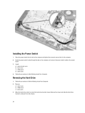
... b) VESA stand c) back cover 3. Installing the Power Switch 1. Remove the screws and slide the hard-drive bracket to the system board. 3. Follow the procedures in After Working Inside Your Computer. Install: a) system board cover b) back cover c) VESA stand d) stand cover ...4. Guide the power-switch cable through the tabs on the computer and tighten the screws to secure the it from the chassis. 24 Removing the Hard Drive 1. Follow the procedures in Before Working Inside Your Computer. 2. Place the power switch into its slot on the computer and connect the power-...
... b) VESA stand c) back cover 3. Installing the Power Switch 1. Remove the screws and slide the hard-drive bracket to the system board. 3. Follow the procedures in After Working Inside Your Computer. Install: a) system board cover b) back cover c) VESA stand d) stand cover ...4. Guide the power-switch cable through the tabs on the computer and tighten the screws to secure the it from the chassis. 24 Removing the Hard Drive 1. Follow the procedures in Before Working Inside Your Computer. 2. Place the power switch into its slot on the computer and connect the power-...
Owner's Manual
Page 25
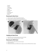
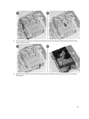
Remove the screws that secure the hard-drive bracket to access the hard-drive cable. Disconnect the hard-drive cable from the harddrive bracket. 25 4. Turn and place the hard drive on the hard-drive bracket to the hard drive and remove the hard drive from the hard drive. 5.
Remove the screws that secure the hard-drive bracket to access the hard-drive cable. Disconnect the hard-drive cable from the harddrive bracket. 25 4. Turn and place the hard drive on the hard-drive bracket to the hard drive and remove the hard drive from the hard drive. 5.
Owner's Manual
Page 26
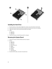
... all the cables connected to the hard drive and place the hard drive into its slot on the computer. 3. Removing the System Board 1. Remove: a) stand cover b) VESA stand c) back cover d) system board cover e) memory f) WLAN card g) heat sink h) hard drive i) optical disk drive 3. Place the hard drive in After Working Inside Your Computer. Connect the hard-drive cable to the system board. 26...
... all the cables connected to the hard drive and place the hard drive into its slot on the computer. 3. Removing the System Board 1. Remove: a) stand cover b) VESA stand c) back cover d) system board cover e) memory f) WLAN card g) heat sink h) hard drive i) optical disk drive 3. Place the hard drive in After Working Inside Your Computer. Connect the hard-drive cable to the system board. 26...
Owner's Manual
Page 31
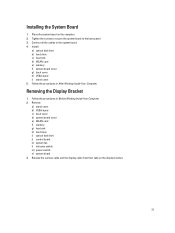
... the system board. 4. Installing the System Board 1. Install: a) optical disk drive b) hard drive c) heat sink d) WLAN card e) memory f) system board cover g) back cover h) VESA stand i) stand cover 5. Remove: a) stand cover b) VESA stand c) back cover d) system board cover e) WLAN card f) memory g) heat sink h) hard drive i) optical disk drive j) control board k) system fan l) intrusion switch m) power switch n) system board...
... the system board. 4. Installing the System Board 1. Install: a) optical disk drive b) hard drive c) heat sink d) WLAN card e) memory f) system board cover g) back cover h) VESA stand i) stand cover 5. Remove: a) stand cover b) VESA stand c) back cover d) system board cover e) WLAN card f) memory g) heat sink h) hard drive i) optical disk drive j) control board k) system fan l) intrusion switch m) power switch n) system board...
Owner's Manual
Page 35
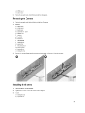
... to secure the camera to the computer and remove it from the computer. m) VESA stand n) stand cover 5. Removing the Camera 1. Follow the procedures in Before Working Inside Your Computer. 2. Remove: a) stand cover b) VESA stand c) back cover d) system board cover e) WLAN card f) memory g) heat sink h) hard drive i) optical drive j) control board k) system fan l) intrusion switch m) power switch...
... to secure the camera to the computer and remove it from the computer. m) VESA stand n) stand cover 5. Removing the Camera 1. Follow the procedures in Before Working Inside Your Computer. 2. Remove: a) stand cover b) VESA stand c) back cover d) system board cover e) WLAN card f) memory g) heat sink h) hard drive i) optical drive j) control board k) system fan l) intrusion switch m) power switch...
Owner's Manual
Page 36
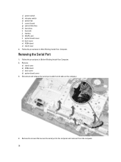
...board g) optical disk drive h) hard drive i) heat sink j) memory k) WLAN card l) system board cover m) back cover n) VESA stand o) stand cover 4. Follow the procedures in After Working Inside Your Computer. Follow the procedures in Before Working Inside Your Computer. 2. Removing the Serial Port 1. Remove: a) stand cover ...b) VESA stand c) back cover d) system board cover 3. Remove the screws that secure the serial port to the computer and...
...board g) optical disk drive h) hard drive i) heat sink j) memory k) WLAN card l) system board cover m) back cover n) VESA stand o) stand cover 4. Follow the procedures in After Working Inside Your Computer. Follow the procedures in Before Working Inside Your Computer. 2. Removing the Serial Port 1. Remove: a) stand cover ...b) VESA stand c) back cover d) system board cover 3. Remove the screws that secure the serial port to the computer and...
Owner's Manual
Page 39
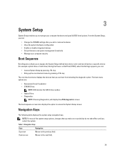
... Dell logo appears, you can: • Access System Setup by pressing key • Bring up the one-time boot menu by pressing key The one-time boot menu displays the devices that you make are : • Removable Drive (if available) • STXXXX Drive NOTE: XXX denotes the SATA drive number...enables you to bypass the System Setup‐defined boot device order and boot directly to a specific device (for example: optical drive or hard drive). Table 1. Navigation Keys Keys Navigation Up arrow Moves to access the System Setup screen. The boot sequence screen also displays ...
... Dell logo appears, you can: • Access System Setup by pressing key • Bring up the one-time boot menu by pressing key The one-time boot menu displays the devices that you make are : • Removable Drive (if available) • STXXXX Drive NOTE: XXX denotes the SATA drive number...enables you to bypass the System Setup‐defined boot device order and boot directly to a specific device (for example: optical drive or hard drive). Table 1. Navigation Keys Keys Navigation Up arrow Moves to access the System Setup screen. The boot sequence screen also displays ...
Statement of Volatility
Page 2
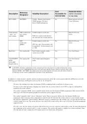
...day information. GPU architecturegDDR3. Volatile memory in off state. Hard drive User replaceable Non Volatile magnetic media, Yes various sizes in the system supports S3 state. Enter S3-S5 state below . Primary power loss (unplugging the power cord and removing the battery) destroys all system contexts. S3 is coming ... the OS will require a complete boot when awakened. No - No GPU uses only. In this state, no system context is no power. Dell systems will remain in different ACPI power states the following is provided (those ACPI power states are S0, S1, S3, S4 and S5): S0...
...day information. GPU architecturegDDR3. Volatile memory in off state. Hard drive User replaceable Non Volatile magnetic media, Yes various sizes in the system supports S3 state. Enter S3-S5 state below . Primary power loss (unplugging the power cord and removing the battery) destroys all system contexts. S3 is coming ... the OS will require a complete boot when awakened. No - No GPU uses only. In this state, no system context is no power. Dell systems will remain in different ACPI power states the following is provided (those ACPI power states are S0, S1, S3, S4 and S5): S0...


