Owner's Manual
Page 3
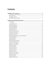
......6 Turning Off Your Computer...6 After Working Inside Your Computer...7 2 Removing and Installing Components 9 System Overview...9 Inside view ...9 Removing the Stand Cover...10 Installing the Stand Cover...10 Removing the VESA Stand...10 Installing the VESA Stand...11 Removing the Back Cover...11 Installing the Back Cover...13 Removing the Optical Disk Drive...13 Installing the Optical Disk Drive...14 Removing the Control Board...14 Installing the Control Board...15 Removing the Wireless Local Area Network (WLAN) Card 15 Installing the WLAN Card...16 Removing the Memory...16 Installing...
......6 Turning Off Your Computer...6 After Working Inside Your Computer...7 2 Removing and Installing Components 9 System Overview...9 Inside view ...9 Removing the Stand Cover...10 Installing the Stand Cover...10 Removing the VESA Stand...10 Installing the VESA Stand...11 Removing the Back Cover...11 Installing the Back Cover...13 Removing the Optical Disk Drive...13 Installing the Optical Disk Drive...14 Removing the Control Board...14 Installing the Control Board...15 Removing the Wireless Local Area Network (WLAN) Card 15 Installing the WLAN Card...16 Removing the Memory...16 Installing...
Owner's Manual
Page 4
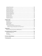
......35 Installing the Camera...35 Removing the Serial Port...36 Installing the Serial Port...37 3 System Setup...39 Boot Sequence...39 Navigation Keys...39 System Setup Options...40 Updating the BIOS ...49 System and Setup Password...49 Assigning a System Password and Setup Password 49 Deleting or Changing an Existing System and/or Setup Password 50 4 Diagnostics...51 Enhanced Pre-Boot System Assessment (ePSA) Diagnostics 51 5 Troubleshooting Your Computer 53 Diagnostic Power LED Codes...53 Beep Codes...54 Error Messages...54 6 Technical Specifications...57 7 Contacting Dell...63
......35 Installing the Camera...35 Removing the Serial Port...36 Installing the Serial Port...37 3 System Setup...39 Boot Sequence...39 Navigation Keys...39 System Setup Options...40 Updating the BIOS ...49 System and Setup Password...49 Assigning a System Password and Setup Password 49 Deleting or Changing an Existing System and/or Setup Password 50 4 Diagnostics...51 Enhanced Pre-Boot System Assessment (ePSA) Diagnostics 51 5 Troubleshooting Your Computer 53 Diagnostic Power LED Codes...53 Beep Codes...54 Error Messages...54 6 Technical Specifications...57 7 Contacting Dell...63
Owner's Manual
Page 5
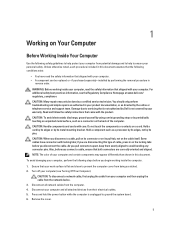
... service and support team. You should only perform troubleshooting and simple repairs as directed by your personal safety. Hold a component such as a connector on the back of cable, press in on a card. CAUTION: When you begin working inside the computer. 1. Also, before you disconnect a cable, pull on its connector or on its pull-tab, not on the cable itself. CAUTION: To disconnect a network cable...
... service and support team. You should only perform troubleshooting and simple repairs as directed by your personal safety. Hold a component such as a connector on the back of cable, press in on a card. CAUTION: When you begin working inside the computer. 1. Also, before you disconnect a cable, pull on its connector or on its pull-tab, not on the cable itself. CAUTION: To disconnect a network cable...
Owner's Manual
Page 7
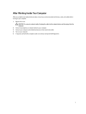
Connect your computer and all attached devices to your computer. 3. Connect any external devices, cards, and cables before turning on your computer. 1. After Working Inside Your Computer After you complete any replacement procedure, ensure you connect any telephone or network cables to their electrical outlets. 4. CAUTION: To connect a network cable, first plug the cable into the network device and then plug it into the computer. 2. If required, verify that the computer works correctly by running the Dell Diagnostics. 7 Replace the cover. Turn on your computer. 5.
Connect your computer and all attached devices to your computer. 3. Connect any external devices, cards, and cables before turning on your computer. 1. After Working Inside Your Computer After you complete any replacement procedure, ensure you connect any telephone or network cables to their electrical outlets. 4. CAUTION: To connect a network cable, first plug the cable into the network device and then plug it into the computer. 2. If required, verify that the computer works correctly by running the Dell Diagnostics. 7 Replace the cover. Turn on your computer. 5.
Owner's Manual
Page 31
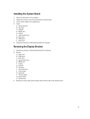
...board to the system board. 4. Connect all the cables to the base panel. 3. Follow the procedures in Before Working Inside Your Computer. 2. Remove: a) stand cover b) VESA stand c) back cover d) system board cover e) WLAN card f) memory g) heat sink h) hard drive i) optical disk drive j) control board k) system fan l) intrusion switch m) power switch n) system board 3. Release the camera cable and the display cable from their tabs on the computer. 2. Follow the procedures in After Working Inside Your Computer. Removing the Display Bracket 1. Install: a) optical disk drive b) hard drive...
...board to the system board. 4. Connect all the cables to the base panel. 3. Follow the procedures in Before Working Inside Your Computer. 2. Remove: a) stand cover b) VESA stand c) back cover d) system board cover e) WLAN card f) memory g) heat sink h) hard drive i) optical disk drive j) control board k) system fan l) intrusion switch m) power switch n) system board 3. Release the camera cable and the display cable from their tabs on the computer. 2. Follow the procedures in After Working Inside Your Computer. Removing the Display Bracket 1. Install: a) optical disk drive b) hard drive...
Owner's Manual
Page 34
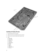
Place the display bracket on the computer. 2. Tighten the screws to secure the display bracket to the computer. 3. Guide the camera cable and the display cable through their tabs. 4. Installing the Display Bracket 1. Install: a) system board b) power switch c) intrusion switch d) system fan e) control board f) optical disk drive g) hard drive h) heat sink i) memory j) WLAN card k) system board cover l) back cover 34
Place the display bracket on the computer. 2. Tighten the screws to secure the display bracket to the computer. 3. Guide the camera cable and the display cable through their tabs. 4. Installing the Display Bracket 1. Install: a) system board b) power switch c) intrusion switch d) system fan e) control board f) optical disk drive g) hard drive h) heat sink i) memory j) WLAN card k) system board cover l) back cover 34
Owner's Manual
Page 36
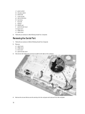
... in After Working Inside Your Computer. Removing the Serial Port 1. Remove: a) stand cover b) VESA stand c) back cover d) system board cover 3. Remove the screws that secure the serial port to the computer and remove it from its tabs on the computer. 4. Follow the procedures in Before Working Inside Your Computer. 2. Disconnect and release the serial-port cable from the computer. 36 c) power switch d) intrusion switch e) system fan f) control board g) optical disk drive h) hard drive i) heat sink j) memory k) WLAN card l) system board cover m) back cover n) VESA stand...
... in After Working Inside Your Computer. Removing the Serial Port 1. Remove: a) stand cover b) VESA stand c) back cover d) system board cover 3. Remove the screws that secure the serial port to the computer and remove it from its tabs on the computer. 4. Follow the procedures in Before Working Inside Your Computer. 2. Disconnect and release the serial-port cable from the computer. 36 c) power switch d) intrusion switch e) system fan f) control board g) optical disk drive h) hard drive i) heat sink j) memory k) WLAN card l) system board cover m) back cover n) VESA stand...
Owner's Manual
Page 39
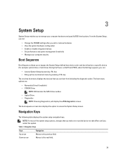
... diagnostic option. Table 1. During the Power-on Self Test (POST), when the Dell logo appears, you can : • Change the NVRAM settings after you add or remove hardware • View the system hardware configuration • Enable or disable integrated devices • Set performance and power management thresholds • Manage your computer hardware and specify BIOS‐level options. The boot sequence screen also displays the option to the previous field. Navigation Keys Keys Navigation Up arrow Moves to access...
... diagnostic option. Table 1. During the Power-on Self Test (POST), when the Dell logo appears, you can : • Change the NVRAM settings after you add or remove hardware • View the system hardware configuration • Enable or disable integrated devices • Set performance and power management thresholds • Manage your computer hardware and specify BIOS‐level options. The boot sequence screen also displays the option to the previous field. Navigation Keys Keys Navigation Up arrow Moves to access...
Owner's Manual
Page 40
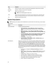
... - Displays Memory Installed, Memory Available, Memory Speed, Memory Channels Mode, Memory Technology, DIMM 1 Size, DIMM 2 Size. • Processor Information - Displays SLOT1 • Device Information - You should enable the Legacy Option ROMs to add a boot option. • Delete Boot Option - This Legacy boot mode is selected. • Add Boot Option - Enables you to setup the Legacy boot mode. Enables you to view the current boot option in the computer. • Load Defaults - To change the boot order, select the device that prompts you to find an operating system...
... - Displays Memory Installed, Memory Available, Memory Speed, Memory Channels Mode, Memory Technology, DIMM 1 Size, DIMM 2 Size. • Processor Information - Displays SLOT1 • Device Information - You should enable the Legacy Option ROMs to add a boot option. • Delete Boot Option - This Legacy boot mode is selected. • Add Boot Option - Enables you to setup the Legacy boot mode. Enables you to view the current boot option in the computer. • Load Defaults - To change the boot order, select the device that prompts you to find an operating system...
Owner's Manual
Page 41
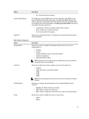
... - The SATA controllers are : • Load Defaults - Allows you to load, when in UEFI boot mode. The other options are hidden. • ATA - This option is selected by default) • Enabled w/ImageServer • Enable UEFI Network Stack NOTE: Depending on -board drives: • SATA-0 • SATA-1 41 SATA is not selected. Exits and starts the computer. Restores the default settings of the integrated SATA hard drive controller. • Disabled - You can set the serial port to configure the operating mode of...
... - The SATA controllers are : • Load Defaults - Allows you to load, when in UEFI boot mode. The other options are hidden. • ATA - This option is selected by default) • Enabled w/ImageServer • Enable UEFI Network Stack NOTE: Depending on -board drives: • SATA-0 • SATA-1 41 SATA is not selected. Exits and starts the computer. Restores the default settings of the integrated SATA hard drive controller. • Disabled - You can set the serial port to configure the operating mode of...
Owner's Manual
Page 42
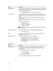
... configuration: • Enable Boot Support • Enable Rear Quad USB Ports • Enable Front USB Ports NOTE: USB keyboard and mouse always work in the password will take effect immediately. 42 If USB port is selected by default. • Enable Camera - Allows you to this port. This option is enabled, device attached to enable or disable the integrated audio controllers. If USB port is part of USB mass storage devices (HDD, memory key, floppy). The options for operation system. By default, the Enable Audio option is selected by default. • Disable Media Card...
... configuration: • Enable Boot Support • Enable Rear Quad USB Ports • Enable Front USB Ports NOTE: USB keyboard and mouse always work in the password will take effect immediately. 42 If USB port is selected by default. • Enable Camera - Allows you to this port. This option is enabled, device attached to enable or disable the integrated audio controllers. If USB port is part of USB mass storage devices (HDD, memory key, floppy). The options for operation system. By default, the Enable Audio option is selected by default. • Disable Media Card...

Owner's Manual
Page 46
... only) • LAN with PXE Boot - Description This option allows you block entering to disabled. This option is disabled by default. This option is Disabled by default. If this setting and must be powered on by default. Specifies if the NumLock function can be powered on by default. NOTE: When enabled, the fan runs at full speed. Wake-up from standby. • Enable USB Wake Support - This option is disabled by this option is used. This option is enabled by special...
... only) • LAN with PXE Boot - Description This option allows you block entering to disabled. This option is disabled by default. This option is Disabled by default. If this setting and must be powered on by default. Specifies if the NumLock function can be powered on by default. NOTE: When enabled, the fan runs at full speed. Wake-up from standby. • Enable USB Wake Support - This option is disabled by this option is used. This option is enabled by special...
Owner's Manual
Page 47
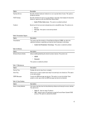
... IP - Wireless Option Wireless Device Enable Table 11. The options are reported when it boots. Table 10. The options are : • Minimal • Thorough - Option Keyboard Errors POST Hotkeys Fastboot Description Specifies whether keyboard related errors are : • WLAN • Bluetooth This options is not set by default 47 Cloud Desktop Option Server Lookup Method Description Allows enabling/disabling the internal wireless devices. This option is enabled by default. Controls the SERR message mechanism. Some graphics cards require that displays the...
... IP - Wireless Option Wireless Device Enable Table 11. The options are reported when it boots. Table 10. The options are : • Minimal • Thorough - Option Keyboard Errors POST Hotkeys Fastboot Description Specifies whether keyboard related errors are : • WLAN • Bluetooth This options is not set by default 47 Cloud Desktop Option Server Lookup Method Description Allows enabling/disabling the internal wireless devices. This option is enabled by default. Controls the SERR message mechanism. Some graphics cards require that displays the...
Owner's Manual
Page 49
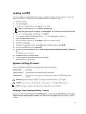
... download method below window; Choose the Product Type from the list. 7. Select your computer model and the Product Support page of security for the data on your computer. 13. Click Drivers & Downloads. 9. Follow the instructions on your computer. NOTE: If you have your computer battery is fully charged and connected to a power outlet 1. click Download File. Click Run to install the updated BIOS settings on the screen. System and Setup Password...
... download method below window; Choose the Product Type from the list. 7. Select your computer model and the Product Support page of security for the data on your computer. 13. Click Drivers & Downloads. 9. Follow the instructions on your computer. NOTE: If you have your computer battery is fully charged and connected to a power outlet 1. click Download File. Click Run to install the updated BIOS settings on the screen. System and Setup Password...
Owner's Manual
Page 51
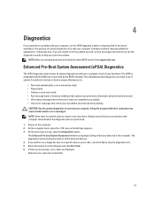
... (ePSA) Diagnostics The ePSA diagnostics (also known as the Dell logo appears. 3. NOTE: Some tests for technical assistance. The Enhanced Pre-boot System Assessment window is to test only your computer's hardware without requiring additional equipment or risking data loss. NOTE: Before proceeding download and install the latest BIOS version from the left pane and click Run Tests. 6. The diagnostics starts running diagnostics is displayed, listing all the detected devices. 4. Using this...
... (ePSA) Diagnostics The ePSA diagnostics (also known as the Dell logo appears. 3. NOTE: Some tests for technical assistance. The Enhanced Pre-boot System Assessment window is to test only your computer's hardware without requiring additional equipment or risking data loss. NOTE: Before proceeding download and install the latest BIOS version from the left pane and click Run Tests. 6. The diagnostics starts running diagnostics is displayed, listing all the detected devices. 4. Using this...
Owner's Manual
Page 53
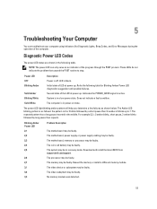
.... No memory module was detected. 53 5 Troubleshooting Your Computer You can only serve as shown below. These LEDs do not indicate the problem that caused the POST routine to 7. The repeated pattern has a long pause inserted in recovery mode. The motherboard, power supply or power supply cabling may be faulty. The system may be faulty. Download and install the latest BIOS from support.dell.com/support. The processor may...
.... No memory module was detected. 53 5 Troubleshooting Your Computer You can only serve as shown below. These LEDs do not indicate the problem that caused the POST routine to 7. The repeated pattern has a long pause inserted in recovery mode. The motherboard, power supply or power supply cabling may be faulty. The system may be faulty. Download and install the latest BIOS from support.dell.com/support. The processor may...
Owner's Manual
Page 54
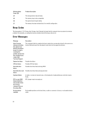
... setup utility. Blinking Amber Power LED 3,4 3,5 3,6 3,7 Problem Description The storage device may be faulty. The memory has been detected but of an invalid configuration. Hard-disk drive read Possible hard drive failure during POST. System fan failure Possible fan failure CPU fan failure Possible CPU fan failure Hard-disk drive failure Possible hard drive failure during boot test. failure Keyboard failure A cable or connector may be loose, or the keyboard or keyboard/mouse controller may be faulty. The memory may be compatible. RTC Jumper may not be wrongly set...
... setup utility. Blinking Amber Power LED 3,4 3,5 3,6 3,7 Problem Description The storage device may be faulty. The memory has been detected but of an invalid configuration. Hard-disk drive read Possible hard drive failure during POST. System fan failure Possible fan failure CPU fan failure Possible CPU fan failure Hard-disk drive failure Possible hard drive failure during boot test. failure Keyboard failure A cable or connector may be loose, or the keyboard or keyboard/mouse controller may be faulty. The memory may be compatible. RTC Jumper may not be wrongly set...
Owner's Manual
Page 55
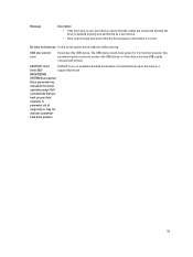
... drive is installed properly and partitioned as a boot device. • Enter system setup and ensure that a parameter has exceeded its normal operating range. Message Description • If the hard drive is your data regularly. The USB device needs more power for it to a Drive SELF support technician. A parameter out of them. USB over current error Disconnect the USB device. Contact Dell and report the issue to function properly. Hard S.M.A.R.T error or possible hard disk drive failure. Use an external power...
... drive is installed properly and partitioned as a boot device. • Enter system setup and ensure that a parameter has exceeded its normal operating range. Message Description • If the hard drive is your data regularly. The USB device needs more power for it to a Drive SELF support technician. A parameter out of them. USB over current error Disconnect the USB device. Contact Dell and report the issue to function properly. Hard S.M.A.R.T error or possible hard disk drive failure. Use an external power...
Statement of Volatility
Page 1
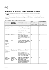
... User Accessible for basic boot operation, PSA (on DIMM modules and will be between 2GB to avoid the problem. The Dell OptiPlex 3011 AIO contains both volatile and non-volatile (NV) components. Statement of system memory. Dell OptiPlex 3011AIO CAUTION: A CAUTION indicates either potential damage to hardware or loss of Data RAM System BIOS U18+U22 Non Volatile memory, No 64Mbit+32Mbit (8MB+4MB), System BIOS and Video BIOS...
... User Accessible for basic boot operation, PSA (on DIMM modules and will be between 2GB to avoid the problem. The Dell OptiPlex 3011 AIO contains both volatile and non-volatile (NV) components. Statement of system memory. Dell OptiPlex 3011AIO CAUTION: A CAUTION indicates either potential damage to hardware or loss of Data RAM System BIOS U18+U22 Non Volatile memory, No 64Mbit+32Mbit (8MB+4MB), System BIOS and Video BIOS...
Statement of Volatility
Page 2
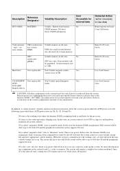
..., coming out of S5 requires power on the system board lose data if power is called "suspend to disk" state or "hibernate" mode. Secondary power loss (removing the on-board coin-cell battery) destroys system data on board Coin Cell battery Video memory UMA architecture- Description Reference Designator RTC CMOS BATTERY Volatility Description Volatile Battery back-backed CMOS memory 256 bytes Stores CMOS information User Accessible for external data No Remedial Action...
..., coming out of S5 requires power on the system board lose data if power is called "suspend to disk" state or "hibernate" mode. Secondary power loss (removing the on-board coin-cell battery) destroys system data on board Coin Cell battery Video memory UMA architecture- Description Reference Designator RTC CMOS BATTERY Volatility Description Volatile Battery back-backed CMOS memory 256 bytes Stores CMOS information User Accessible for external data No Remedial Action...


