Service Manual
Page 5
Contents 1 Before You Begin Preparing to Work Inside the Computer 10 Recommended Tools 11 Screw Identification 12 2 Removing and Replacing Parts Components 16 Hard Drive 17 Removing the Hard Drive 17 Replacing the Hard Drive 17 Memory Module 18 Removing ...
Contents 1 Before You Begin Preparing to Work Inside the Computer 10 Recommended Tools 11 Screw Identification 12 2 Removing and Replacing Parts Components 16 Hard Drive 17 Removing the Hard Drive 17 Replacing the Hard Drive 17 Memory Module 18 Removing ...

Service Manual
Page 9
SECTION 1 Before You Begin Preparing to Work Inside the Computer Recommended Tools Screw Identification www.dell.com | support.dell.com
SECTION 1 Before You Begin Preparing to Work Inside the Computer Recommended Tools Screw Identification www.dell.com | support.dell.com
Service Manual
Page 12
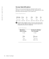
Screw Placement Hard Drive Door Security: (1 each) Keyboard to lay out and keep track of screws and the sizes. The placemat provides the number of the component screws. www.dell.com | support.dell.com Screw Identification When you must use a screw of the correct diameter and length. Make sure that the screw is properly aligned with its corresponding hole, and avoid overtightening. Screw Identification NOTICE: When reinstalling a screw, you are removing and replacing components, photocopy the placemat as a tool to Bottom Case Assembly: (5 each) 12 Be fo r e Yo u Be g in
Screw Placement Hard Drive Door Security: (1 each) Keyboard to lay out and keep track of screws and the sizes. The placemat provides the number of the component screws. www.dell.com | support.dell.com Screw Identification When you must use a screw of the correct diameter and length. Make sure that the screw is properly aligned with its corresponding hole, and avoid overtightening. Screw Identification NOTICE: When reinstalling a screw, you are removing and replacing components, photocopy the placemat as a tool to Bottom Case Assembly: (5 each) 12 Be fo r e Yo u Be g in
Service Manual
Page 13
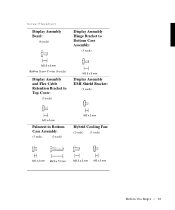
Screw Placement Display Assembly Bezel: (6 each) Display Assembly Hinge Bracket to Bottom Case Assembly: (5 each) Rubber Screw Covers (6 each) Display Assembly and Flex Cable Retention Bracket to Top Cover: (5 each) Display Assembly EMI Shield Bracket: (2 each) Palmrest to Bottom Case Assembly: (5 each) (3 each) Hybrid Cooling Fan: (2 each) (1 each) B e fo re You Be gin 13
Screw Placement Display Assembly Bezel: (6 each) Display Assembly Hinge Bracket to Bottom Case Assembly: (5 each) Rubber Screw Covers (6 each) Display Assembly and Flex Cable Retention Bracket to Top Cover: (5 each) Display Assembly EMI Shield Bracket: (2 each) Palmrest to Bottom Case Assembly: (5 each) (3 each) Hybrid Cooling Fan: (2 each) (1 each) B e fo re You Be gin 13

Service Manual
Page 17
...drive bay until the drive door is very sensitive to Work Inside the Computer" before performing the following procedure. 1 Remove the M3 x 5-mm screw from the hard drive door. 2 Slide the drive door up until the drive assembly tabs disengage from electrical outlets, and remove any attached devices from...with the computer case. Handle the assembly by touching an unpainted metal surface on the computer. Hard Drive bottom of computer M3 x 5-mm screw hard drive door Removing the Hard Drive NOTICE: Disconnect the computer and any installed batteries. Removing and Repl aci ng Part s 17
...drive bay until the drive door is very sensitive to Work Inside the Computer" before performing the following procedure. 1 Remove the M3 x 5-mm screw from the hard drive door. 2 Slide the drive door up until the drive assembly tabs disengage from electrical outlets, and remove any attached devices from...with the computer case. Handle the assembly by touching an unpainted metal surface on the computer. Hard Drive bottom of computer M3 x 5-mm screw hard drive door Removing the Hard Drive NOTICE: Disconnect the computer and any installed batteries. Removing and Repl aci ng Part s 17
Service Manual
Page 18
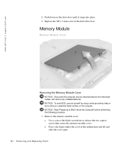
... Computer" before performing the following procedure. 1 Remove the memory module cover: a Use a coin or flat-blade screwdriver to release the two captive screws that secure the memory module cover. NOTICE: To avoid ESD, ground yourself by using a wrist grounding strap or by touching an unpainted metal surface... on the drive door until it snaps into place. 3 Replace the M3 x 5-mm screw in the hard drive door. Memory Module Memory Module Cover Removing the Memory Module Cover NOTICE: Disconnect the computer and any attached devices from ...
... Computer" before performing the following procedure. 1 Remove the memory module cover: a Use a coin or flat-blade screwdriver to release the two captive screws that secure the memory module cover. NOTICE: To avoid ESD, ground yourself by using a wrist grounding strap or by touching an unpainted metal surface... on the drive door until it snaps into place. 3 Replace the M3 x 5-mm screw in the hard drive door. Memory Module Memory Module Cover Removing the Memory Module Cover NOTICE: Disconnect the computer and any attached devices from ...
Service Manual
Page 19
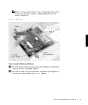
NOTE: The screw labeled with the "circle K" in the middle of the memory module cover secures the keyboard assembly and does not secure the memory module cover. Removing and Repl aci ng Part s 19 NOTICE: To avoid ESD, ground yourself by using a wrist grounding strap or by touching an unpainted metal surface on the computer. Memory Modules JDIM 1 JDIM 2 inner tabs (2 per socket) memory module sockets (2) Removing the Memory Modules NOTICE: Disconnect the computer and any attached devices from electrical outlets, and remove any installed batteries.
NOTE: The screw labeled with the "circle K" in the middle of the memory module cover secures the keyboard assembly and does not secure the memory module cover. Removing and Repl aci ng Part s 19 NOTICE: To avoid ESD, ground yourself by using a wrist grounding strap or by touching an unpainted metal surface on the computer. Memory Modules JDIM 1 JDIM 2 inner tabs (2 per socket) memory module sockets (2) Removing the Memory Modules NOTICE: Disconnect the computer and any attached devices from electrical outlets, and remove any installed batteries.
Service Manual
Page 20
...card assembly before performing the following procedure. 1 Remove the memory module cover. 2 To release a memory module from the socket. www.dell.com | support.dell.com NOTICE: Read "Preparing to Work Inside the Computer" before the system board assembly can be connected to the system's internal antenna..., press the memory module's edge connector firmly into the memory module socket. 3 Pivot the memory module down and tighten the two captive screws. A mini-PCI card assembly may consist of the memory module socket just far enough for the memory module to the wiring harness as ...
...card assembly before performing the following procedure. 1 Remove the memory module cover. 2 To release a memory module from the socket. www.dell.com | support.dell.com NOTICE: Read "Preparing to Work Inside the Computer" before the system board assembly can be connected to the system's internal antenna..., press the memory module's edge connector firmly into the memory module socket. 3 Pivot the memory module down and tighten the two captive screws. A mini-PCI card assembly may consist of the memory module socket just far enough for the memory module to the wiring harness as ...

Service Manual
Page 23
... to Work Inside the Computer" before performing the following procedure. 1 Remove the hard drive. 2 Turn the computer over, and remove the five M2.5 x 12-mm screws from electrical outlets, and remove any attached devices from the holes labeled "circle K." 3 Turn the computer over and open the display. Keyboard Assembly Removing the...
... to Work Inside the Computer" before performing the following procedure. 1 Remove the hard drive. 2 Turn the computer over, and remove the five M2.5 x 12-mm screws from electrical outlets, and remove any attached devices from the holes labeled "circle K." 3 Turn the computer over and open the display. Keyboard Assembly Removing the...
Service Manual
Page 26
...NOTICE: To avoid ESD, ground yourself by using a wrist grounding strap or by touching an unpainted metal surface on the computer. www.dell.com | support.dell.com NOTICE: Position the keyboard flex cable so it is correctly installed. NOTE: Always remove and replace the display panel as a ...complete assembly. the display assembly hinges pass through the back of the palmrest. 5 Reinstall the five M2.5 x 12-mm screws in the bottom case assembly. ...
...NOTICE: To avoid ESD, ground yourself by using a wrist grounding strap or by touching an unpainted metal surface on the computer. www.dell.com | support.dell.com NOTICE: Position the keyboard flex cable so it is correctly installed. NOTE: Always remove and replace the display panel as a ...complete assembly. the display assembly hinges pass through the back of the palmrest. 5 Reinstall the five M2.5 x 12-mm screws in the bottom case assembly. ...
Service Manual
Page 27
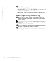
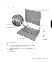
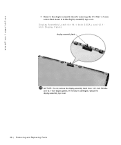
Display Assembly M2 x 3-mm screws (2) EMI shield bracket LCD flex cable connector display-assembly top cover (14.1-inch display assembly shown) center control cover M2.5 x 5-mm screws (5) bottom case assembly 1 Remove the hard drive. 2 Remove the center control cover. a Use a scribe to lift the right edge of the center control cover and pry it loose from the bottom case assembly. 3 Close the display. b Lift the center control cover up and away from the bottom case assembly. Removing and Repl aci ng Part s 27
Display Assembly M2 x 3-mm screws (2) EMI shield bracket LCD flex cable connector display-assembly top cover (14.1-inch display assembly shown) center control cover M2.5 x 5-mm screws (5) bottom case assembly 1 Remove the hard drive. 2 Remove the center control cover. a Use a scribe to lift the right edge of the center control cover and pry it loose from the bottom case assembly. 3 Close the display. b Lift the center control cover up and away from the bottom case assembly. Removing and Repl aci ng Part s 27
Service Manual
Page 28
...dell.com 4 From the back of the connector may damage resistors and compromise EMI protection in the system. Pressing on the top left and right ends of the connector (see "Display Assembly"). 9 Lift the display assembly from the bottom case assembly. There are two screws on the right hinge and three screws...assembly approximately 180 degrees and support the display assembly so it does not open past this position. 6 Remove the two M2 x 3-mm screws that secure the EMI shield bracket to the system board assembly. 7 Remove the flex cable EMI shield retention bracket that covers the display-feed...
...dell.com 4 From the back of the connector may damage resistors and compromise EMI protection in the system. Pressing on the top left and right ends of the connector (see "Display Assembly"). 9 Lift the display assembly from the bottom case assembly. There are two screws on the right hinge and three screws...assembly approximately 180 degrees and support the display assembly so it does not open past this position. 6 Remove the two M2 x 3-mm screws that secure the EMI shield bracket to the system board assembly. 7 Remove the flex cable EMI shield retention bracket that covers the display-feed...
Service Manual
Page 30
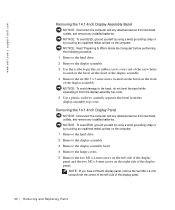
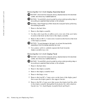
www.dell.com | support.dell.com Removing the 14.1-Inch Display Assembly Bezel NOTICE: Disconnect the computer and any attached devices from electrical outlets, and remove any installed batteries. NOTE: If you have a Hitachi display panel, remove the two M2 x 4-mm screws from the center of the left... hard drive. 2 Remove the display assembly. 3 Remove the display assembly bezel. 4 Remove the hinge covers. 5 Remove the two M2 x 4-mm screws on the left side of the display panel. NOTICE: To avoid ESD, ground yourself by using a wrist grounding strap or by touching an unpainted metal...
www.dell.com | support.dell.com Removing the 14.1-Inch Display Assembly Bezel NOTICE: Disconnect the computer and any attached devices from electrical outlets, and remove any installed batteries. NOTE: If you have a Hitachi display panel, remove the two M2 x 4-mm screws from the center of the left... hard drive. 2 Remove the display assembly. 3 Remove the display assembly bezel. 4 Remove the hinge covers. 5 Remove the two M2 x 4-mm screws on the left side of the display panel. NOTICE: To avoid ESD, ground yourself by using a wrist grounding strap or by touching an unpainted metal...
Service Manual
Page 31
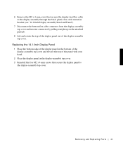
... hand. 2 Place the display panel in the display-assembly top cover. 3 Reinstall the five M2 x 4-mm screws that secures the display-feed flex cable to the display-assembly top cover. 6 Remove the M2 x 4-mm screw that secure the display panel to the display assembly through the black plastic flex cable retention bracket...
... hand. 2 Place the display panel in the display-assembly top cover. 3 Reinstall the five M2 x 4-mm screws that secures the display-feed flex cable to the display-assembly top cover. 6 Remove the M2 x 4-mm screw that secure the display panel to the display assembly through the black plastic flex cable retention bracket...
Service Manual
Page 34
NOTICE: To avoid damage to the bezel, do not bend the bezel while separating it from the display-assembly top cover. www.dell.com | support.dell.com Removing the 12.1-Inch Display Assembly Bezel NOTICE: Disconnect the computer and any attached devices from electrical outlets, and remove any installed batteries. ...the computer. 1 Remove the hard drive. 2 Remove the display assembly. 3 Remove the display assembly bezel. 4 Remove the hinge covers. 5 Remove the four M3 x 3-mm screws on the front of the display panel that secure the display panel to the support bracket. 6 Remove the M2 x 4-mm...
NOTICE: To avoid damage to the bezel, do not bend the bezel while separating it from the display-assembly top cover. www.dell.com | support.dell.com Removing the 12.1-Inch Display Assembly Bezel NOTICE: Disconnect the computer and any attached devices from electrical outlets, and remove any installed batteries. ...the computer. 1 Remove the hard drive. 2 Remove the display assembly. 3 Remove the display assembly bezel. 4 Remove the hinge covers. 5 Remove the four M3 x 3-mm screws on the front of the display panel that secure the display panel to the support bracket. 6 Remove the M2 x 4-mm...
Service Manual
Page 35
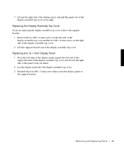
... pull the panel out of the panel with your hand. 2 Lay the display panel into the display-assembly top cover. 3 Reinstall the four M3 x 3-mm screws that secure the display panel to the support bracket. Replacing the 12.1-Inch Display Panel 1 Place the left edge of the display panel against the... left side of the display-assembly top cover and the two M2 x 4-mm screws on the left side of the support bracket in the display-assembly top cover, and elevate the right side of the display-assembly top cover...
... pull the panel out of the panel with your hand. 2 Lay the display panel into the display-assembly top cover. 3 Reinstall the four M3 x 3-mm screws that secure the display panel to the support bracket. Replacing the 12.1-Inch Display Panel 1 Place the left edge of the display panel against the... left side of the display-assembly top cover and the two M2 x 4-mm screws on the left side of the support bracket in the display-assembly top cover, and elevate the right side of the display-assembly top cover...
Service Manual
Page 36
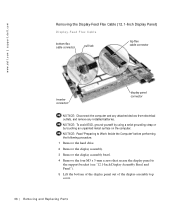
www.dell.com | support.dell.com Removing the Display-Feed Flex Cable (12.1-Inch Display Panel) Display-Feed Flex Cable bottom flex cable connector pull tab top flex cable connector ... the Computer" before performing the following procedure. 1 Remove the hard drive. 2 Remove the display assembly. 3 Remove the display assembly bezel. 4 Remove the four M3 x 3-mm screws that secure the display panel to the support bracket (see "12.1-Inch Display Assembly Bezel and Panel"). 5 Lift the bottom of the display panel out...
www.dell.com | support.dell.com Removing the Display-Feed Flex Cable (12.1-Inch Display Panel) Display-Feed Flex Cable bottom flex cable connector pull tab top flex cable connector ... the Computer" before performing the following procedure. 1 Remove the hard drive. 2 Remove the display assembly. 3 Remove the display assembly bezel. 4 Remove the four M3 x 3-mm screws that secure the display panel to the support bracket (see "12.1-Inch Display Assembly Bezel and Panel"). 5 Lift the bottom of the display panel out...
Service Manual
Page 37
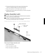
... up on the computer. Removing and Repl aci ng Part s 37 Display Assembly Latch for 14.1-Inch XGA Display Panels display assembly latch M2.5 x 5-mm screws (2) Removing the Display Assembly Latch 1 Remove the hard drive. 2 Remove the display assembly. 3 Remove the display assembly bezel. Display Assembly Latch NOTICE: Disconnect the computer...
... up on the computer. Removing and Repl aci ng Part s 37 Display Assembly Latch for 14.1-Inch XGA Display Panels display assembly latch M2.5 x 5-mm screws (2) Removing the Display Assembly Latch 1 Remove the hard drive. 2 Remove the display assembly. 3 Remove the display assembly bezel. Display Assembly Latch NOTICE: Disconnect the computer...
Service Manual
Page 38
www.dell.com | support.dell.com 4 Remove the display assembly latch by removing the two M2.5 x 5-mm screws that secure it to the display-assembly top cover. If the latch is damaged, replace the display-assembly top cover. 38 Removi ng and Replacing Parts Display Assembly Latch for 14.1-Inch SXGA+ and 12.1Inch Display Panels display assembly latch NOTICE: Do not remove the display assembly latch from 14.1-inch SXGA+ and 12.1-inch display panels.
www.dell.com | support.dell.com 4 Remove the display assembly latch by removing the two M2.5 x 5-mm screws that secure it to the display-assembly top cover. If the latch is damaged, replace the display-assembly top cover. 38 Removi ng and Replacing Parts Display Assembly Latch for 14.1-Inch SXGA+ and 12.1Inch Display Panels display assembly latch NOTICE: Do not remove the display assembly latch from 14.1-inch SXGA+ and 12.1-inch display panels.
Service Manual
Page 41
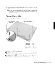
Removing and Repl aci ng Part s 41 Palmrest Assembly Removing the Palmrest Assembly Screws M2.5 x 12-mm screws (3) M2 x 3-mm screws (2) Removing the Palmrest Assembly NOTICE: Disconnect the computer and any attached devices from electrical outlets, and remove any installed batteries. NOTICE: To avoid ESD, ground ...
Removing and Repl aci ng Part s 41 Palmrest Assembly Removing the Palmrest Assembly Screws M2.5 x 12-mm screws (3) M2 x 3-mm screws (2) Removing the Palmrest Assembly NOTICE: Disconnect the computer and any attached devices from electrical outlets, and remove any installed batteries. NOTICE: To avoid ESD, ground ...

