Owners Manual
Page 4
Removing the Display Assembly (Touch)...27 Installing the Display Assembly (Touch)...28 Removing the Display Assembly...29 Installing the Display Assembly...30 Removing the Power Connector...30 Installing the Power Connector...31 Removing the Display Bezel...31 Installing the Display Bezel...32 Removing the Display Hinges...33 Installing the Display Hinges...34 Removing... Pre-Boot System Assessment (ePSA) Diagnostics 47 Device Status Lights...47 Battery Status Lights...48 Beep Codes...48 LED Error Codes...48 5 Specifications...51 6 Contacting Dell...57
Removing the Display Assembly (Touch)...27 Installing the Display Assembly (Touch)...28 Removing the Display Assembly...29 Installing the Display Assembly...30 Removing the Power Connector...30 Installing the Power Connector...31 Removing the Display Bezel...31 Installing the Display Bezel...32 Removing the Display Hinges...33 Installing the Display Hinges...34 Removing... Pre-Boot System Assessment (ePSA) Diagnostics 47 Device Status Lights...47 Battery Status Lights...48 Beep Codes...48 LED Error Codes...48 5 Specifications...51 6 Contacting Dell...57
Owners Manual
Page 6
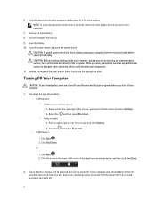
Press the power button to dissipate static electricity, which could harm internal components. 11. Click the - Click Start . 2. 6. While you shut down on a flat work , periodically touch an ...: To avoid losing data, save and close all open files and exit all attached devices are turned off your operating system, press and hold the power button for about 6 seconds to turn them off when you work surface. Click Shut Down. Ensure that the computer and all open programs before opening...
Press the power button to dissipate static electricity, which could harm internal components. 11. Click the - Click Start . 2. 6. While you shut down on a flat work , periodically touch an ...: To avoid losing data, save and close all open files and exit all attached devices are turned off your operating system, press and hold the power button for about 6 seconds to turn them off when you work surface. Click Shut Down. Ensure that the computer and all open programs before opening...
Owners Manual
Page 10
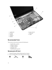
speakers 4. heatsink 6. system board 2. I/O board 3. WLAN card 8. system fan 5. Follow the procedures in this document may require the following tools: • Small flat-blade screwdriver • #0 Phillips screwdriver • #1 Phillips screwdriver • Small plastic scribe • Flash BIOS update program CD Removing the SD Card 1. display Recommended Tools The procedures in Before Working Inside Your Computer. 2. power connector 7. 1. Press in on the SD memory card to release it from the computer. 10
speakers 4. heatsink 6. system board 2. I/O board 3. WLAN card 8. system fan 5. Follow the procedures in this document may require the following tools: • Small flat-blade screwdriver • #0 Phillips screwdriver • #1 Phillips screwdriver • Small plastic scribe • Flash BIOS update program CD Removing the SD Card 1. display Recommended Tools The procedures in Before Working Inside Your Computer. 2. power connector 7. 1. Press in on the SD memory card to release it from the computer. 10
Owners Manual
Page 18
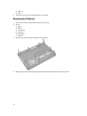
Removing the Palmrest 1. Remove: a) battery b) SD card c) access panel d) hard drive e) optical-drive f) keyboard 3. Flip the computer and disconnect the touchpad cable and power-button cable from the system board. 18 a) keyboard b) battery 5. Follow the procedures in After Working Inside Your Computer. Remove the screws that secure the palmrest to the computer. 4. Follow the procedures in Before Working Inside Your Computer. 2.
Removing the Palmrest 1. Remove: a) battery b) SD card c) access panel d) hard drive e) optical-drive f) keyboard 3. Flip the computer and disconnect the touchpad cable and power-button cable from the system board. 18 a) keyboard b) battery 5. Follow the procedures in After Working Inside Your Computer. Remove the screws that secure the palmrest to the computer. 4. Follow the procedures in Before Working Inside Your Computer. 2.

Owners Manual
Page 20
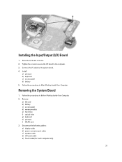
... to secure the palmrest to the system board. 4. Remove the screw that secures the I/O board to the system board. 3. Connect the touchpad cable and the power-button cables to the computer and lift the I/O board from the system board. Disconnect the I /O) Board 1. Removing the Input/Output (I /O cable from the computer. 20...
... to secure the palmrest to the system board. 4. Remove the screw that secures the I/O board to the system board. 3. Connect the touchpad cable and the power-button cables to the computer and lift the I/O board from the system board. Disconnect the I /O) Board 1. Removing the Input/Output (I /O cable from the computer. 20...
Owners Manual
Page 21
... the system board. 4. Remove: a) SD card b) battery c) access panel d) memory module e) hard drive f) optical drive g) keyboard h) palmrest i) WLAN card 3. Disconnect the following cables: a) display cable b) power-connector port cable c) speaker cable d) I /O) Board 1.
... the system board. 4. Remove: a) SD card b) battery c) access panel d) memory module e) hard drive f) optical drive g) keyboard h) palmrest i) WLAN card 3. Disconnect the following cables: a) display cable b) power-connector port cable c) speaker cable d) I /O) Board 1.

Owners Manual
Page 22
Align the system board in its place on the system board: a) touch cable (for touch computer only) b) I/O board cable c) speaker cable d) power-connector cable e) display cable 4. Connect the following cables to the computer. 3. 4. Lift the system board from the computer. Install: a) WLAN card 22 Installing the System Board 1. Tighten the screw to secure the system board to their connectors on the computer. 2. Remove the screw that secures the system board to the computer.
Align the system board in its place on the system board: a) touch cable (for touch computer only) b) I/O board cable c) speaker cable d) power-connector cable e) display cable 4. Connect the following cables to the computer. 3. 4. Lift the system board from the computer. Install: a) WLAN card 22 Installing the System Board 1. Tighten the screw to secure the system board to their connectors on the computer. 2. Remove the screw that secures the system board to the computer.

Owners Manual
Page 30
... computer. 6. Affix the tape that secures the display and camera cable to the computer. 3. Follow the procedures in Before Working Inside Your Computer. 2. Removing the Power Connector 1. Connect the antennae cables to the system board. 5. Remove: a) battery b) access panel c) hard drive d) optical drive 30 Connect the display and...
... computer. 6. Affix the tape that secures the display and camera cable to the computer. 3. Follow the procedures in Before Working Inside Your Computer. 2. Removing the Power Connector 1. Connect the antennae cables to the system board. 5. Remove: a) battery b) access panel c) hard drive d) optical drive 30 Connect the display and...

Owners Manual
Page 31
... drive g) access panel h) battery 5. Follow the procedures in the illustration: a) Disconnect the power-connector cable and release the power-connector cable from the computer. Remove: a) battery b) SD card c) access panel 31 Installing the Power Connector 1. Removing the Display Bezel 1. b) Remove the power connector from the routing channel. Follow the procedures in the computer. 2. Align...
... drive g) access panel h) battery 5. Follow the procedures in the illustration: a) Disconnect the power-connector cable and release the power-connector cable from the computer. Remove: a) battery b) SD card c) access panel 31 Installing the Power Connector 1. Removing the Display Bezel 1. b) Remove the power connector from the routing channel. Follow the procedures in the computer. 2. Align...
Owners Manual
Page 39
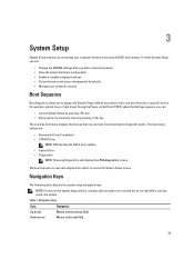
... (POST), when the Dell logo appears, you can boot from including the diagnostic option. Table 1. From the System Setup, you can: • Change the NVRAM settings after you add or remove hardware • View the system hardware configuration • Enable or disable integrated devices • Set performance and power management thresholds •...
... (POST), when the Dell logo appears, you can boot from including the diagnostic option. Table 1. From the System Setup, you can: • Change the NVRAM settings after you add or remove hardware • View the system hardware configuration • Enable or disable integrated devices • Set performance and power management thresholds •...
Owners Manual
Page 41
... default option is Enabled Function Key Behavior Specifies the behavior of the optical drive. The default option is Enabled Integrated NIC Enable or disable the power supply to either ATA or AHCI. The default option is Enabled Virtualization Enable or disable the Intel Virtualization feature. Displays the type of each option...
... default option is Enabled Function Key Behavior Specifies the behavior of the optical drive. The default option is Enabled Integrated NIC Enable or disable the power supply to either ATA or AHCI. The default option is Enabled Virtualization Enable or disable the Intel Virtualization feature. Displays the type of each option...
Owners Manual
Page 43
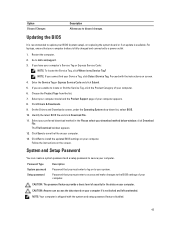
...stored on your computer. CAUTION: Anyone can create a system password and a setup password to secure your computer appears. 8. Restart the computer. 2. Go to dell.com/support. 3. NOTE: If you have your computer's Service Tag or Express Service Code: NOTE: To locate the Service Tag, click Where is fully ...charged and connected to a power outlet 1. Choose the Product Type from the list. 7. Select your computer model and the Product Support page of security for the data on to...
...stored on your computer. CAUTION: Anyone can create a system password and a setup password to secure your computer appears. 8. Restart the computer. 2. Go to dell.com/support. 3. NOTE: If you have your computer's Service Tag or Express Service Code: NOTE: To locate the Service Tag, click Where is fully ...charged and connected to a power outlet 1. Choose the Product Type from the list. 7. Select your computer model and the Product Support page of security for the data on to...
Owners Manual
Page 44
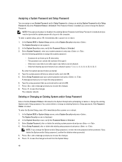
...Password Status is Locked. Select Setup Password, type your system password, and press or . To enter the System Setup, press immediately after a power-on or reboot. 1. NOTE: If you entered earlier and click OK. 5. The password can have up to assign the system password: ...- Only the following guidelines to 32 characters. - If you to save the changes. 6. To enter a system setup, press immediately after a power-on or reboot. 1. A password can contain the numbers 0 through 9. - Press and a message prompts you entered earlier and click OK. 7. You ...
...Password Status is Locked. Select Setup Password, type your system password, and press or . To enter the System Setup, press immediately after a power-on or reboot. 1. NOTE: If you entered earlier and click OK. 5. The password can have up to assign the system password: ...- Only the following guidelines to 32 characters. - If you to save the changes. 6. To enter a system setup, press immediately after a power-on or reboot. 1. A password can contain the numbers 0 through 9. - Press and a message prompts you entered earlier and click OK. 7. You ...
Owners Manual
Page 47
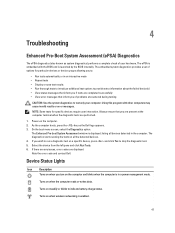
... or writes data. NOTE: Some tests for particular devices or device groups allowing you to: • Run tests automatically or in a power management mode. Select the device from the left pane and click Run Tests. 6. If you of options for specific devices require user interaction...boot System Assessment window is enabled. 47 4 Troubleshooting Enhanced Pre-Boot System Assessment (ePSA) Diagnostics The ePSA diagnostics (also known as the Dell logo appears. 3. The ePSA is embedded with other computers may cause invalid results or error messages. If there are any issues, error ...
... or writes data. NOTE: Some tests for particular devices or device groups allowing you to: • Run tests automatically or in a power management mode. Select the device from the left pane and click Run Tests. 6. If you of options for specific devices require user interaction...boot System Assessment window is enabled. 47 4 Troubleshooting Enhanced Pre-Boot System Assessment (ePSA) Diagnostics The ePSA diagnostics (also known as the Dell logo appears. 3. The ePSA is embedded with other computers may cause invalid results or error messages. If there are any issues, error ...
Owners Manual
Page 48
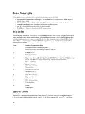
.... cache test failure Processor failure 8 Display Display failure LED Error Codes Diagnostic LED codes are communicated via the Power Button LED. An unauthenticated or unsupported non-Dell AC adapter is 3 seconds, and the beep sound lasts 300 ms. After each beep and each set of beeps, the BIOS should... detect if the user presses the power button. Battery in charge mode with AC adapter present. • Light off - Temporary...
.... cache test failure Processor failure 8 Display Display failure LED Error Codes Diagnostic LED codes are communicated via the Power Button LED. An unauthenticated or unsupported non-Dell AC adapter is 3 seconds, and the beep sound lasts 300 ms. After each beep and each set of beeps, the BIOS should... detect if the user presses the power button. Battery in charge mode with AC adapter present. • Light off - Temporary...

Owners Manual
Page 49
This pattern continues until the system is powered off. cache test failure Processor failure 8 Display Display failure 49 Code 1 Cause and Troubleshooting Steps System board: BIOS ROM failure System board failure, covers BIOS ... Clock test failure , Gate A20 failure , Super I/O chip failure , Keyboard controller test failure System board failure 4 RAM Read/Write failure Memory failure 5 Real-time clock power fail CMOS battery failure 6 Video BIOS test failure Video card failure 7 CPU - LED blinks two times followed by a pause, blinks two times, pause, etc.
This pattern continues until the system is powered off. cache test failure Processor failure 8 Display Display failure 49 Code 1 Cause and Troubleshooting Steps System board: BIOS ROM failure System board failure, covers BIOS ... Clock test failure , Gate A20 failure , Super I/O chip failure , Keyboard controller test failure System board failure 4 RAM Read/Write failure Memory failure 5 Real-time clock power fail CMOS battery failure 6 Video BIOS test failure Video card failure 7 CPU - LED blinks two times followed by a pause, blinks two times, pause, etc.
Owners Manual
Page 53
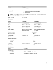
... Japan 90 US 102, Brazil 105, UK 103 and Japan 106 53 Feature Latitude 3540 Description • one USB 2.0 port • two USB 3.0 ports (rear one 4-in the documentation shipped with window debug) • two USB 2.0 port NOTE: The powered USB 3.0 connector also supports Microsoft Kernel Debugging. The ports are identified in -1 slot...
... Japan 90 US 102, Brazil 105, UK 103 and Japan 106 53 Feature Latitude 3540 Description • one USB 2.0 port • two USB 3.0 ports (rear one 4-in the documentation shipped with window debug) • two USB 2.0 port NOTE: The powered USB 3.0 connector also supports Microsoft Kernel Debugging. The ports are identified in -1 slot...
Owners Manual
Page 54
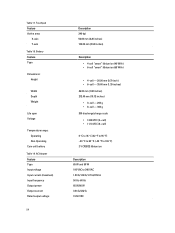
... Life span Voltage Temperature range: Operating Non-Operating Coin-cell battery Table 19. AC Adapter Feature Type Input voltage Input current (maximum) Input frequency Output power Output current Rated output voltage 54 Description 240 dpi 56.00 mm (2.20 inches) 100.00 mm (3.94 inches) Description • 4-cell "smart" lithium ion...
... Life span Voltage Temperature range: Operating Non-Operating Coin-cell battery Table 19. AC Adapter Feature Type Input voltage Input current (maximum) Input frequency Output power Output current Rated output voltage 54 Description 240 dpi 56.00 mm (2.20 inches) 100.00 mm (3.94 inches) Description • 4-cell "smart" lithium ion...
Setup Guide
Page 1
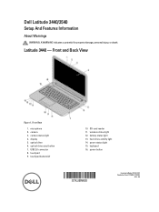
.... camera status light 4. keyboard 16. Dell Latitude 3440/3540 Setup And Features Information About Warnings WARNING: A WARNING indicates a potential for property damage, personal injury, or death. Front View 1. touchpad buttons (2) 10. microphone 2. Front and Back View Figure 1. optical-drive eject button 7. SD card reader 11. power status light 15. Latitude 3440 - display 5. USB 2.0 connector 8. hard...
.... camera status light 4. keyboard 16. Dell Latitude 3440/3540 Setup And Features Information About Warnings WARNING: A WARNING indicates a potential for property damage, personal injury, or death. Front View 1. touchpad buttons (2) 10. microphone 2. Front and Back View Figure 1. optical-drive eject button 7. SD card reader 11. power status light 15. Latitude 3440 - display 5. USB 2.0 connector 8. hard...
Setup Guide
Page 2
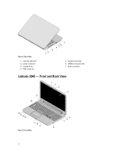
power connector 3. VGA connector 5. Back View 1. security cable slot 2. cooling vents 4. Front and Back View Figure 3. network connector 6. audio connector Latitude 3540 - USB 3.0 connectors (2) 7. Front View 2 Figure 2.
power connector 3. VGA connector 5. Back View 1. security cable slot 2. cooling vents 4. Front and Back View Figure 3. network connector 6. audio connector Latitude 3540 - USB 3.0 connectors (2) 7. Front View 2 Figure 2.


