Owner's Manual
Page 14
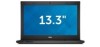
4. Align the display panel in its original position on the display assembly. 14 Replace the adhesive tape that secures the low-voltage differential signalling (LVDS) connection to the display panel. 4. Remove the display panel from the display panel. 7.... tape that secures the LVDS connection to the display panel. 6. Connect the display cable to the display panel and attach the adhesive tape to the keyboard. 5. Rotate the display panel over to secure the connection. 2. Installing The Display Panel 1. Connect the low-voltage differential signalling (LVDS) cable to the ...
4. Align the display panel in its original position on the display assembly. 14 Replace the adhesive tape that secures the low-voltage differential signalling (LVDS) connection to the display panel. 4. Remove the display panel from the display panel. 7.... tape that secures the LVDS connection to the display panel. 6. Connect the display cable to the display panel and attach the adhesive tape to the keyboard. 5. Rotate the display panel over to secure the connection. 2. Installing The Display Panel 1. Connect the low-voltage differential signalling (LVDS) cable to the ...
Owner's Manual
Page 24
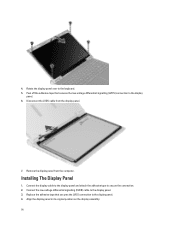
...Replace the HDMI board into its compartment. 2. Follow the procedures in Before Working on Your Computer. 2. Remove the screws that secure the HDMI board to the system board. 4. Installing The High-Definition Multimedia Interface (HDMI) Board 1. Install: a) display assembly b) system board c) display assembly d) palmrest e) memory f) hard drive g) keyboard... h) base cover i) secure digital (SD) card j) battery 3. Removing The Speakers 1. Remove: a) battery b) secure digital (SD) card c) base cover d) keyboard e) hard drive f) memory g) palmrest...
...Replace the HDMI board into its compartment. 2. Follow the procedures in Before Working on Your Computer. 2. Remove the screws that secure the HDMI board to the system board. 4. Installing The High-Definition Multimedia Interface (HDMI) Board 1. Install: a) display assembly b) system board c) display assembly d) palmrest e) memory f) hard drive g) keyboard... h) base cover i) secure digital (SD) card j) battery 3. Removing The Speakers 1. Remove: a) battery b) secure digital (SD) card c) base cover d) keyboard e) hard drive f) memory g) palmrest...
Owner's Manual
Page 27
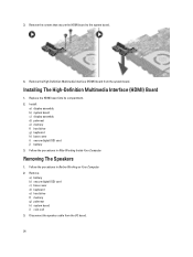
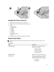
...; Processor Information • Device Information Battery Information Boot Sequence Displays the charge status of the battery. Installing The Power Connector 1. Replace the power connector port into its installed devices, the items listed in place. 3. Follow the procedures in which the computer attempts ...order in After Working Inside Your Computer. Install: a) system board b) display assembly c) palmrest d) memory e) hard drive f) keyboard g) base cover h) decure digital (SD) card i) battery 4. All the below options are selected. • Diskette Drive • Internal HDD 27
...; Processor Information • Device Information Battery Information Boot Sequence Displays the charge status of the battery. Installing The Power Connector 1. Replace the power connector port into its installed devices, the items listed in place. 3. Follow the procedures in which the computer attempts ...order in After Working Inside Your Computer. Install: a) system board b) display assembly c) palmrest d) memory e) hard drive f) keyboard g) base cover h) decure digital (SD) card i) battery 4. All the below options are selected. • Diskette Drive • Internal HDD 27


