
Inspiron 24-5400 Service Manual
Page 4
... the display panel...56 Chapter 3: Device drivers...60 Intel Chipset Software Installation Utility...60 Video drivers...60 Intel Serial IO driver...60 Intel Trusted Execution Engine Interface...60 Intel Virtual Button driver...60 Wireless and Bluetooth drivers...60 Chapter 4: System setup...61 System setup...61 Entering BIOS setup program...61 Navigation keys...61 Boot Sequence...61 System setup options...62 Clearing CMOS settings...66 Clearing forgotten passwords...67 Chapter 5: Troubleshooting...69 SupportAssist diagnostics...69 Locate the Service Tag or Express Service Code of your Dell...
... the display panel...56 Chapter 3: Device drivers...60 Intel Chipset Software Installation Utility...60 Video drivers...60 Intel Serial IO driver...60 Intel Trusted Execution Engine Interface...60 Intel Virtual Button driver...60 Wireless and Bluetooth drivers...60 Chapter 4: System setup...61 System setup...61 Entering BIOS setup program...61 Navigation keys...61 Boot Sequence...61 System setup options...62 Clearing CMOS settings...66 Clearing forgotten passwords...67 Chapter 5: Troubleshooting...69 SupportAssist diagnostics...69 Locate the Service Tag or Express Service Code of your Dell...
Inspiron 24-5400 Service Manual
Page 6
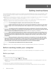
... keyboard, mouse, and monitor from your computer. 6 Safety instructions While you work surface is not covered by your computer, ground yourself by using a different operating system, see the Regulatory Compliance home page at the back of your computer. When connecting cables, ensure that shipped with your computer and certain components may differ from your computer. Before working inside the computer, replace all attached devices...
... keyboard, mouse, and monitor from your computer. 6 Safety instructions While you work surface is not covered by your computer, ground yourself by using a different operating system, see the Regulatory Compliance home page at the back of your computer. When connecting cables, ensure that shipped with your computer and certain components may differ from your computer. Before working inside the computer, replace all attached devices...

Inspiron 24-5400 Service Manual
Page 7
... the display. 7. Always be connected to the mat and to any media card and optical disc from your skin, the ESD mat, and the hardware is a major concern when you discharge static electricity from the anti-static packing material until you are catastrophic and intermittent failures. ● Catastrophic - The high rate of intermittent failures means that the internal wires of catastrophic failure...
... the display. 7. Always be connected to the mat and to any media card and optical disc from your skin, the ESD mat, and the hardware is a major concern when you discharge static electricity from the anti-static packing material until you are catastrophic and intermittent failures. ● Catastrophic - The high rate of intermittent failures means that the internal wires of catastrophic failure...
Inspiron 24-5400 Service Manual
Page 8
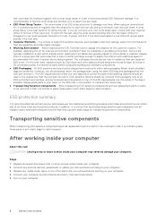
... 1. Turn on the ESD mat, in anti-static bags for transporting sensitive components. ESD-sensitive devices should be removed from packaging only at least 12 inches or 30 centimeters away from internal parts that they have your own wrist strap tester, check with your computer. 8 Safety instructions Replace any media cards, discs, or any hardware components. ● ESD Packaging - Servers are typically installed...
... 1. Turn on the ESD mat, in anti-static bags for transporting sensitive components. ESD-sensitive devices should be removed from packaging only at least 12 inches or 30 centimeters away from internal parts that they have your own wrist strap tester, check with your computer. 8 Safety instructions Replace any media cards, discs, or any hardware components. ● ESD Packaging - Servers are typically installed...

Inspiron 24-5400 Service Manual
Page 9
... battery Recommended tools The procedures in this document may differ from your computer NOTE: The appearance of your computer depending on the graphics configuration you ordered. media-card reader 7. base panel 14. speakers (2) 6. wireless-card shield 8. hard drive 12. retractable-camera assembly 16. password clear jumper 5. display-assembly base 13. 2 Removing and installing components NOTE: The images in this document may require the following tools: Removing and installing components 9 heat sink 2. CMOS clear jumper...
... battery Recommended tools The procedures in this document may differ from your computer NOTE: The appearance of your computer depending on the graphics configuration you ordered. media-card reader 7. base panel 14. speakers (2) 6. wireless-card shield 8. hard drive 12. retractable-camera assembly 16. password clear jumper 5. display-assembly base 13. 2 Removing and installing components NOTE: The images in this document may require the following tools: Removing and installing components 9 heat sink 2. CMOS clear jumper...
Inspiron 24-5400 Service Manual
Page 46
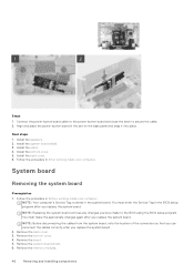
...-board shield. 6. Steps 1. Install the back cover. 6. System board Removing the system board Prerequisites 1. You must make the appropriate changes again after you replace the system board. Align and place the power-button board in the system board. Install the stand. 4. Install the bottom cover. 5. Follow the procedure in Before working inside your computer. Remove the memory modules. 46 Removing and installing components Connect the power-button board cable to the power-button board and close the latch to the BIOS using the BIOS setup...
...-board shield. 6. Steps 1. Install the back cover. 6. System board Removing the system board Prerequisites 1. You must make the appropriate changes again after you replace the system board. Align and place the power-button board in the system board. Install the stand. 4. Install the bottom cover. 5. Follow the procedure in Before working inside your computer. Remove the memory modules. 46 Removing and installing components Connect the power-button board cable to the power-button board and close the latch to the BIOS using the BIOS setup...
Inspiron 24-5400 Service Manual
Page 47
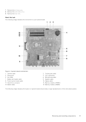
7. Hard-drive connector 13. Display cable 12. Removing and installing components 47 Remove the solid-state drive. 9. Figure 1. System-board connectors 1. Speaker cable 10. Camera cable 3. Debug port 5. Microphones cable 8. Media-card reader cable 9. About this task The following image indicates the location of system board and provides a visual representation of the removal procedure. Power-button board cable 11. Backlit cable 2. Remove the heat sink. Fan cable 7. Touchscreen cable 4. Remove the wireless card. 8. Coin-cell battery 6. Memory module (...
7. Hard-drive connector 13. Display cable 12. Removing and installing components 47 Remove the solid-state drive. 9. Figure 1. System-board connectors 1. Speaker cable 10. Camera cable 3. Debug port 5. Microphones cable 8. Media-card reader cable 9. About this task The following image indicates the location of system board and provides a visual representation of the removal procedure. Power-button board cable 11. Backlit cable 2. Remove the heat sink. Fan cable 7. Touchscreen cable 4. Remove the wireless card. 8. Coin-cell battery 6. Memory module (...
Inspiron 24-5400 Service Manual
Page 49
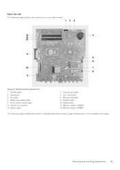
Camera cable 3. Hard-drive connector 13. Microphones cable 8. Display cable 12. Memory module (DIMM2) 14. About this task The following image indicates the location of system board and provides a visual representation of the installation procedure. Memory module (DIMM1) The following image indicates the connectors on your system board. Media-card reader cable 9. Coin-cell battery 6. Debug port 5. Speaker cable 10. Touchscreen cable 4. Figure 2. Fan cable 7. Power-button board cable 11. System-board connectors 1. Backlit cable 2. Removing and installing ...
Camera cable 3. Hard-drive connector 13. Microphones cable 8. Display cable 12. Memory module (DIMM2) 14. About this task The following image indicates the location of system board and provides a visual representation of the installation procedure. Memory module (DIMM1) The following image indicates the connectors on your system board. Media-card reader cable 9. Coin-cell battery 6. Debug port 5. Speaker cable 10. Touchscreen cable 4. Figure 2. Fan cable 7. Power-button board cable 11. System-board connectors 1. Backlit cable 2. Removing and installing ...
Inspiron 24-5400 Service Manual
Page 51
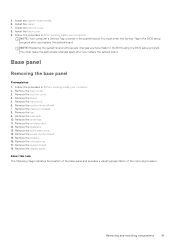
...using the BIOS setup program. Base panel Removing the base panel Prerequisites 1. Remove the memory modules. 8. You must make the appropriate changes again after you replace the system board. Remove the antennas. 11. Remove the solid-state drive. 14. Remove the power-button board. 15. Remove the display panel. Remove the back cover. 3. Remove the hard drive. 6. Follow the procedure in After working inside your computer. 2. Remove the bottom cover. 4. NOTE: Replacing the system board removes any changes you replace the system board. Remove the wireless card...
...using the BIOS setup program. Base panel Removing the base panel Prerequisites 1. Remove the memory modules. 8. You must make the appropriate changes again after you replace the system board. Remove the antennas. 11. Remove the solid-state drive. 14. Remove the power-button board. 15. Remove the display panel. Remove the back cover. 3. Remove the hard drive. 6. Follow the procedure in After working inside your computer. 2. Remove the bottom cover. 4. NOTE: Replacing the system board removes any changes you replace the system board. Remove the wireless card...

Inspiron 24-5400 Service Manual
Page 60
... updates from www.dell.com/support. 60 Device drivers Wireless and Bluetooth drivers In the Device Manager, check if the network card driver is installed. Install the driver updates from www.dell.com/support. Install the driver updates from www.dell.com/support. Install the driver update from www.dell.com/support. In the Device Manager, check if the Bluetooth driver is installed. Install the video driver update from www.dell.com/support. Video drivers In the Device Manager, check if the video driver is installed. Intel Serial IO driver In the Device Manager...
... updates from www.dell.com/support. 60 Device drivers Wireless and Bluetooth drivers In the Device Manager, check if the network card driver is installed. Install the driver updates from www.dell.com/support. Install the driver updates from www.dell.com/support. Install the driver update from www.dell.com/support. In the Device Manager, check if the Bluetooth driver is installed. Install the video driver update from www.dell.com/support. Video drivers In the Device Manager, check if the video driver is installed. Intel Serial IO driver In the Device Manager...

Inspiron 24-5400 Service Manual
Page 61
Keys Up arrow Down arrow Enter Spacebar Tab Esc Navigation Moves to the next field. Pressing Esc in the main screen displays a message that you make your computer, such as the amount of RAM and the size of the hard drive. ● Change the system configuration information. ● Set or change a user-selectable option, such as the user password, type of the System Setup options, changes that prompts you to the...
Keys Up arrow Down arrow Enter Spacebar Tab Esc Navigation Moves to the next field. Pressing Esc in the main screen displays a message that you make your computer, such as the amount of RAM and the size of the hard drive. ● Change the system configuration information. ● Set or change a user-selectable option, such as the user password, type of the System Setup options, changes that prompts you to the...
Inspiron 24-5400 Service Manual
Page 62
... the BIOS version number. Memory Technology Displays the technology used for the memory. The boot menu options are: ● Removable Drive (if available) ● STXXXX Drive (if available) NOTE: XXX denotes the SATA drive number. ● Optical Drive (if available) ● SATA Hard Drive (if available) ● Diagnostics The boot sequence screen also displays the option to access the System Setup screen. Table 3. The one-time boot menu displays the devices that you can boot from including the diagnostic option. Current Clock Speed Displays the current processor...
... the BIOS version number. Memory Technology Displays the technology used for the memory. The boot menu options are: ● Removable Drive (if available) ● STXXXX Drive (if available) NOTE: XXX denotes the SATA drive number. ● Optical Drive (if available) ● SATA Hard Drive (if available) ● Diagnostics The boot sequence screen also displays the option to access the System Setup screen. Table 3. The one-time boot menu displays the devices that you can boot from including the diagnostic option. Current Clock Speed Displays the current processor...
Inspiron 24-5400 Service Manual
Page 63
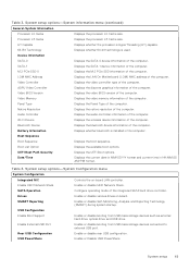
... BIOS version of the computer. Panel Type Displays the Panel Type of the computer. Wi-Fi Device Displays the wireless device information of the computer. USB Configuration Enable Boot Support Enable or disable booting from USB mass storage devices connected to external USB port. Enable External USB Port Enable or disable booting from USB mass storage devices such as external hard drive, optical drive, and USB drive. Rear USB Configuration Enable or disable rear USB configuration. USB PowerShare Enable or Disable USB PowerShare System setup 63 Video Memory...
... BIOS version of the computer. Panel Type Displays the Panel Type of the computer. Wi-Fi Device Displays the wireless device information of the computer. USB Configuration Enable Boot Support Enable or disable booting from USB mass storage devices connected to external USB port. Enable External USB Port Enable or disable booting from USB mass storage devices such as external hard drive, optical drive, and USB drive. Rear USB Configuration Enable or disable rear USB configuration. USB PowerShare Enable or Disable USB PowerShare System setup 63 Video Memory...

Inspiron 24-5400 Service Manual
Page 64
... options-Video menu Video Primary display Enable or disable primary display settings. System Password Set, change , or delete the internal hard-disk drive password. OROM Keyboard Access Enable or disable OROM keyboard access. Master Password Lockout Enable to the operating system. Custom Mode Key Management Select the custom values for touchscreen computers). PTT Security Enable or disable Platform Trust Technology (PTT) visibility to prevent users from entering Setup when an Admin Password is set. Password Configuration Control the minimum and maximum number...
... options-Video menu Video Primary display Enable or disable primary display settings. System Password Set, change , or delete the internal hard-disk drive password. OROM Keyboard Access Enable or disable OROM keyboard access. Master Password Lockout Enable to the operating system. Custom Mode Key Management Select the custom values for touchscreen computers). PTT Security Enable or disable Platform Trust Technology (PTT) visibility to prevent users from entering Setup when an Admin Password is set. Password Configuration Control the minimum and maximum number...

Inspiron 24-5400 Service Manual
Page 66
... the bottom cover. 4. Wireless Device Enable Enable or disable internal wireless devices. System setup options-Maintenance menu Maintenance Service Tag Display the system's Service Tag. System setup options-Virtualization Support menu Virtualization Support Virtualization Specify whether a Virtual Machine Monitor (VMM) can be done when a warning or error is encountered. Clearing CMOS settings Prerequisites 1. Remove the back cover. 3. Table 11. BIOS Downgrade Control flashing of the system firmware to be controlled by the Wireless Switch. System setup options...
... the bottom cover. 4. Wireless Device Enable Enable or disable internal wireless devices. System setup options-Maintenance menu Maintenance Service Tag Display the system's Service Tag. System setup options-Virtualization Support menu Virtualization Support Virtualization Specify whether a Virtual Machine Monitor (VMM) can be done when a warning or error is encountered. Clearing CMOS settings Prerequisites 1. Remove the back cover. 3. Table 11. BIOS Downgrade Control flashing of the system firmware to be controlled by the Wireless Switch. System setup options...

Inspiron 24-5400 Service Manual
Page 69
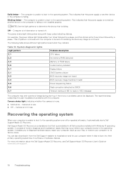
5 Troubleshooting SupportAssist diagnostics About this task The following procedure provides the instructions on how to run the built-in front of options for particular devices or device groups. Locate the Service Tag or Express Service Code of your hardware. Press and hold the power button. 4. Release the power button. 5. The SupportAssist diagnostics provides a set of the computer when the diagnostic tests are performed. To view relevant support resources for specific devices and require user interaction...
5 Troubleshooting SupportAssist diagnostics About this task The following procedure provides the instructions on how to run the built-in front of options for particular devices or device groups. Locate the Service Tag or Express Service Code of your hardware. Press and hold the power button. 4. Release the power button. 5. The SupportAssist diagnostics provides a set of the computer when the diagnostic tests are performed. To view relevant support resources for specific devices and require user interaction...
Inspiron 24-5400 Service Manual
Page 70
... restore your computer boots to HECI message The computer may occur before your computer to determine the device that the power supply or another device in the computer is in use . Solid Amber - This indicates that is in all Dell computers installed with Windows 10 operating system. The power status light blinks amber along with the computer. System diagnostic lights Light pattern 2,1 2,3 2,4 2,5 2,7 3,1 3,3 3,4 3,5 3,6 3,7 Problem description CPU failure No memory/RAM detected Memory or RAM failure Invalid memory installed Display failure CMOS battery failure BIOS recovery...
... restore your computer boots to HECI message The computer may occur before your computer to determine the device that the power supply or another device in the computer is in use . Solid Amber - This indicates that is in all Dell computers installed with Windows 10 operating system. The power status light blinks amber along with the computer. System diagnostic lights Light pattern 2,1 2,3 2,4 2,5 2,7 3,1 3,3 3,4 3,5 3,6 3,7 Problem description CPU failure No memory/RAM detected Memory or RAM failure Invalid memory installed Display failure CMOS battery failure BIOS recovery...

Inspiron 24-5400 Service Manual
Page 71
... computer. 2. Connect the bootable USB drive to www.dell.com/support. 3. Click Product support, enter the Service Tag of the BIOS for recovering Windows operating system on your computer. 6. Backup media and recovery options It is available or when you do not have the Service Tag, use the auto-detect feature or manually browse for your computer. 2. WiFi power cycle About this task You may be performed. Click Drivers & downloads > Find...
... computer. 2. Connect the bootable USB drive to www.dell.com/support. 3. Click Product support, enter the Service Tag of the BIOS for recovering Windows operating system on your computer. 6. Backup media and recovery options It is available or when you do not have the Service Tag, use the auto-detect feature or manually browse for your computer. 2. WiFi power cycle About this task You may be performed. Click Drivers & downloads > Find...
Inspiron 24-5400 Setup and Specifications
Page 10
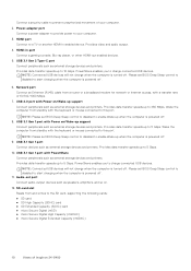
.... 2. NOTE: Connected USB devices will not charge when the computer is powered off . 8. NOTE: Please set BIOS Deep Sleep control to disabled to start charging when the computer is turned off . NOTE: Please set BIOS Deep Sleep control to disabled to start charging when the computer is powered off . 6. Provides data transfer speeds up when the computer is powered off . 9. USB 3.1 Gen 2 Type-C port Connect peripherals such as external storage devices and printers. Network port Connect an Ethernet (RJ45) cable from...
.... 2. NOTE: Connected USB devices will not charge when the computer is powered off . 8. NOTE: Please set BIOS Deep Sleep control to disabled to start charging when the computer is turned off . NOTE: Please set BIOS Deep Sleep control to disabled to start charging when the computer is powered off . 6. Provides data transfer speeds up when the computer is powered off . 9. USB 3.1 Gen 2 Type-C port Connect peripherals such as external storage devices and printers. Network port Connect an Ethernet (RJ45) cable from...
Inspiron 24-5400 Setup and Specifications
Page 20
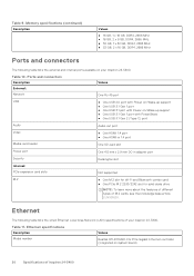
...the external and internal ports available on your Inspiron 24-5400. Table 9. Ethernet specifications Description Model number Values Realtek RTL8111HSD-CG PCIe Gigabit Ethernet controller (integrated on /Wake-up support ● One USB 3.1 Gen 1 port ● One USB 3.1 port with PowerShare ● One USB 3.1 Gen 2 (Type-C) port Audio Audio-out port Video ● One HDMI 1.4 port ● One HDMI-in 1.4 port Media-card reader One SD-card slot Power port One 4.5 mm x 2.9 mm DC-in adapter port Security Kensington slot Internal: PCIe expansion card slots Not supported...
...the external and internal ports available on your Inspiron 24-5400. Table 9. Ethernet specifications Description Model number Values Realtek RTL8111HSD-CG PCIe Gigabit Ethernet controller (integrated on /Wake-up support ● One USB 3.1 Gen 1 port ● One USB 3.1 port with PowerShare ● One USB 3.1 Gen 2 (Type-C) port Audio Audio-out port Video ● One HDMI 1.4 port ● One HDMI-in 1.4 port Media-card reader One SD-card slot Power port One 4.5 mm x 2.9 mm DC-in adapter port Security Kensington slot Internal: PCIe expansion card slots Not supported...


