Owner's Manual
Page 8
... 144 Replacing the Battery 144 Power Supply 146 Replacing the Power Supply 146 Processor 148 Removing the Processor 148 Installing the Processor 150 I/O Panel 153 Removing the I/O Panel 153 Installing the I/O Panel 154 Processor Fan 155 Removing the Processor Fan 155 Installing the Processor Fan 158 Chassis Fan 160 Removing the Chassis Fan 160 Replacing the...
... 144 Replacing the Battery 144 Power Supply 146 Replacing the Power Supply 146 Processor 148 Removing the Processor 148 Installing the Processor 150 I/O Panel 153 Removing the I/O Panel 153 Installing the I/O Panel 154 Processor Fan 155 Removing the Processor Fan 155 Installing the Processor Fan 158 Chassis Fan 160 Removing the Chassis Fan 160 Replacing the...
Owner's Manual
Page 42
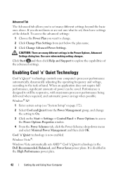
... savings when possible. Use care when making setting changes. Enabling Cool 'n' Quiet Technology Cool 'n' Quiet™ technology controls your computer's processor performance automatically, dynamically adjusting the operating frequency and voltage, according to set , then leave settings at hand. If you want to access...and select Minimal Power Management and then click OK. Click Start and then click Help and Support to set many different settings in the Dell Recommended, Balanced, and Power Saver power plans. Windows® XP: 1 Enter system setup (see "System Setup" on page 172)....
... savings when possible. Use care when making setting changes. Enabling Cool 'n' Quiet Technology Cool 'n' Quiet™ technology controls your computer's processor performance automatically, dynamically adjusting the operating frequency and voltage, according to set , then leave settings at hand. If you want to access...and select Minimal Power Management and then click OK. Click Start and then click Help and Support to set many different settings in the Dell Recommended, Balanced, and Power Saver power plans. Windows® XP: 1 Enter system setup (see "System Setup" on page 172)....
Owner's Manual
Page 82
... for assistance). The floppy disk may be loose. System Messages NOTE: If the message you received is not listed in the table, see "Removing the Processor Fan" on page 155). Replace battery (see "Replacing the Battery" on page 144 or see "Getting Help" on page 183 for assistance). C P U F A N F A I L U R E - D I S K E T T E D R I V E 0 S E E K F A I L U R E - H A R D - The computer failed...
... for assistance). The floppy disk may be loose. System Messages NOTE: If the message you received is not listed in the table, see "Removing the Processor Fan" on page 155). Replace battery (see "Replacing the Battery" on page 144 or see "Getting Help" on page 183 for assistance). C P U F A N F A I L U R E - D I S K E T T E D R I V E 0 S E E K F A I L U R E - H A R D - The computer failed...
Owner's Manual
Page 102
... or contacts on your own personal safety. NOTICE: Only a certified service technician should perform repairs on a card. Hold a component such as a processor by its edges, not by its metal mounting bracket. If your computer and attached devices did not automatically turn off when you shut down your... operating system shutdown process finishes. 3 Ensure that the computer and any attached devices are turned off . 3 Ensure that is not authorized by Dell is not covered by its pins. Hold a card by its edges or by your operating system, press and hold the power button for at...
... or contacts on your own personal safety. NOTICE: Only a certified service technician should perform repairs on a card. Hold a component such as a processor by its edges, not by its metal mounting bracket. If your computer and attached devices did not automatically turn off when you shut down your... operating system shutdown process finishes. 3 Ensure that the computer and any attached devices are turned off . 3 Ensure that is not authorized by Dell is not covered by its pins. Hold a card by its edges or by your operating system, press and hold the power button for at...

Owner's Manual
Page 114
1 Follow the procedures in "Before You Begin" on page 101. 2 Press the securing clip at each end of the memory module connector. 1 2 3 1 memory connector farthest 2 securing clips (2) from processor (DIMM_2) 3 connector 3 Align the notch on the bottom of the module with the crossbar in the connector. 3 2 1 1 cutouts (2) 3 notch 4 2 memory module 4 crossbar 114 Removing and Installing Parts
1 Follow the procedures in "Before You Begin" on page 101. 2 Press the securing clip at each end of the memory module connector. 1 2 3 1 memory connector farthest 2 securing clips (2) from processor (DIMM_2) 3 connector 3 Align the notch on the bottom of the module with the crossbar in the connector. 3 2 1 1 cutouts (2) 3 notch 4 2 memory module 4 crossbar 114 Removing and Installing Parts

Owner's Manual
Page 148
... a network cable, first plug the cable into the network device and then plug it into the computer. 15 Connect your computer's electronic components. Processor CAUTION: Before you touch any of the procedures in this section, follow the safety instructions located in "Before You Begin" on page 101. 2... the clamp grip from your body before you begin any of the power supply. Removing the Processor 1 Follow the procedures in the Product Information Guide. You can do so by running the Dell Diagnostics (see "Replacing the Computer Cover" on page 165). 11 Reconnect the DC power cables...
... a network cable, first plug the cable into the network device and then plug it into the computer. 15 Connect your computer's electronic components. Processor CAUTION: Before you touch any of the procedures in this section, follow the safety instructions located in "Before You Begin" on page 101. 2... the clamp grip from your body before you begin any of the power supply. Removing the Processor 1 Follow the procedures in the Product Information Guide. You can do so by running the Dell Diagnostics (see "Replacing the Computer Cover" on page 165). 11 Reconnect the DC power cables...
Owner's Manual
Page 149
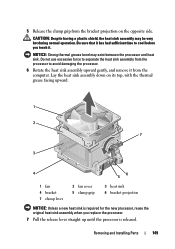
.... 1 2 7 3 4 6 5 1 fan 4 bracket 7 clamp lever 2 fan cover 5 clamp grip 3 heat sink 6 bracket projection NOTICE: Unless a new heat sink is required for the new processor, reuse the original heat sink assembly when you touch it from the computer. 5 Release the clamp grip from the... processor to cool before you replace the processor. 7 Pull the release lever straight up until the processor is released. Removing and Installing Parts 149 Be sure that it has had sufficient time to avoid ...
.... 1 2 7 3 4 6 5 1 fan 4 bracket 7 clamp lever 2 fan cover 5 clamp grip 3 heat sink 6 bracket projection NOTICE: Unless a new heat sink is required for the new processor, reuse the original heat sink assembly when you touch it from the computer. 5 Release the clamp grip from the... processor to cool before you replace the processor. 7 Pull the release lever straight up until the processor is released. Removing and Installing Parts 149 Be sure that it has had sufficient time to avoid ...
Owner's Manual
Page 150
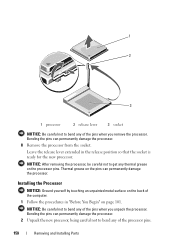
...the procedures in the release position so that the socket is ready for the new processor. NOTICE: After removing the processor, be careful not to bend any of the pins when you remove the processor. Leave the release lever extended in "Before You Begin" on the pins can ...permanently damage the processor. 1 2 3 1 processor 2 release lever 3 socket NOTICE: Be careful not to bend any of the processor pins. 150 Removing and Installing Parts Bending the...
...the procedures in the release position so that the socket is ready for the new processor. NOTICE: After removing the processor, be careful not to bend any of the pins when you remove the processor. Leave the release lever extended in "Before You Begin" on the pins can ...permanently damage the processor. 1 2 3 1 processor 2 release lever 3 socket NOTICE: Be careful not to bend any of the processor pins. 150 Removing and Installing Parts Bending the...
Owner's Manual
Page 151
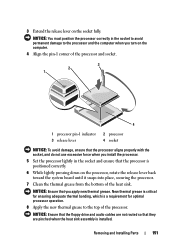
... the computer when you turn on the computer. 4 Align the pin-1 corner of the processor and socket. 3 2 1 4 1 processor pin-1 indicator 3 release lever 2 processor 4 socket NOTICE: To avoid damage, ensure that the processor aligns properly with the socket, and do not use excessive force when you apply new thermal ... sink assembly is positioned correctly. 6 While lightly pressing down on the socket fully. NOTICE: Ensure that you install the processor. 5 Set the processor lightly in the socket to avoid permanent damage to the top of the heat sink. 3 Extend the release lever on the...
... the computer when you turn on the computer. 4 Align the pin-1 corner of the processor and socket. 3 2 1 4 1 processor pin-1 indicator 3 release lever 2 processor 4 socket NOTICE: To avoid damage, ensure that the processor aligns properly with the socket, and do not use excessive force when you apply new thermal ... sink assembly is positioned correctly. 6 While lightly pressing down on the socket fully. NOTICE: Ensure that you install the processor. 5 Set the processor lightly in the socket to avoid permanent damage to the top of the heat sink. 3 Extend the release lever on the...

Owner's Manual
Page 155
...to cool before you touch any of your computer, discharge static electricity from the electrical outlet before you touch them. Removing the Processor Fan 1 Follow the procedures in the Product Information Guide. Be sure that they have had sufficient time to components inside your ...electrical shock, laceration by touching an unpainted metal surface on page 103). 1 2 3 1 I/O panel 2 I/O panel clamp 3 I/O panel clamp slot Processor Fan CAUTION: Before you begin any of the procedures in this section, follow the safety instructions in "Before You Begin" on page 101. 2 Remove the...
...to cool before you touch any of your computer, discharge static electricity from the electrical outlet before you touch them. Removing the Processor Fan 1 Follow the procedures in the Product Information Guide. Be sure that they have had sufficient time to components inside your ...electrical shock, laceration by touching an unpainted metal surface on page 103). 1 2 3 1 I/O panel 2 I/O panel clamp 3 I/O panel clamp slot Processor Fan CAUTION: Before you begin any of the procedures in this section, follow the safety instructions in "Before You Begin" on page 101. 2 Remove the...
Owner's Manual
Page 156
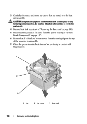
... to cool before you touch it. 4 Remove heat sink (see "System Board Components" on page 148). 5 Disconnect the processor fan cable from the heat sink surface previously in contact with the processor. 1 2 3 1 fan 2 fan cover 3 heat sink 156 Removing and Installing Parts 3 Carefully disconnect and move any... cables that all cables have been removed from the routing clips on the top of the processor fan assembly. 7 Clean the grease from the system board (see step 6 of "Removing the Processor" on page 107). 6 Ensure that are routed over the heat sink assembly.
... to cool before you touch it. 4 Remove heat sink (see "System Board Components" on page 148). 5 Disconnect the processor fan cable from the heat sink surface previously in contact with the processor. 1 2 3 1 fan 2 fan cover 3 heat sink 156 Removing and Installing Parts 3 Carefully disconnect and move any... cables that all cables have been removed from the routing clips on the top of the processor fan assembly. 7 Clean the grease from the system board (see step 6 of "Removing the Processor" on page 107). 6 Ensure that are routed over the heat sink assembly.
Owner's Manual
Page 158
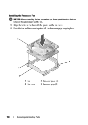
Installing the Processor Fan NOTICE: When reinstalling the fan, ensure that you do not pinch the wires that run between the system board and the fan. 1 Align the holes in the fan with the guides on the fan cover. 2 Press the fan and fan cover together till the fan cover grips snap in place. 1 4 2 3 1 fan 3 fan cover 2 fan cover guide (2) 4 fan cover grips (4) 158 Removing and Installing Parts
Installing the Processor Fan NOTICE: When reinstalling the fan, ensure that you do not pinch the wires that run between the system board and the fan. 1 Align the holes in the fan with the guides on the fan cover. 2 Press the fan and fan cover together till the fan cover grips snap in place. 1 4 2 3 1 fan 3 fan cover 2 fan cover guide (2) 4 fan cover grips (4) 158 Removing and Installing Parts
Owner's Manual
Page 159
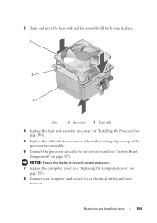
Removing and Installing Parts 159 NOTICE: Ensure that were removed from the routing clips on top of "Installing the Processor" on page 150). 5 Replace the cables that the fan is correctly seated and secure. 7 Replace the computer cover (see "Replacing the Computer Cover" on page ... the heat sink and fan assembly till both snap in place. 1 2 3 1 fan 2 fan cover 3 heat sink 4 Replace the heat sink assembly (see step 9 of the processor fan assembly. 6 Connect the processor fan cable to an electrical outlet, and turn them on page 107).
Removing and Installing Parts 159 NOTICE: Ensure that were removed from the routing clips on top of "Installing the Processor" on page 150). 5 Replace the cables that the fan is correctly seated and secure. 7 Replace the computer cover (see "Replacing the Computer Cover" on page ... the heat sink and fan assembly till both snap in place. 1 2 3 1 fan 2 fan cover 3 heat sink 4 Replace the heat sink assembly (see step 9 of the processor fan assembly. 6 Connect the processor fan cable to an electrical outlet, and turn them on page 107).

Owner's Manual
Page 162
... 103). 3 Remove any add-in cards on the system board (see "Removing a PCI/PCI Express Card" on page 121). 4 Remove the processor and the heat sink assembly (see "Removing the Processor" on page 148). 5 Remove the memory modules (see "Replacing the Computer Cover" on page 115) and document which memory module is...
... 103). 3 Remove any add-in cards on the system board (see "Removing a PCI/PCI Express Card" on page 121). 4 Remove the processor and the heat sink assembly (see "Removing the Processor" on page 148). 5 Remove the memory modules (see "Replacing the Computer Cover" on page 115) and document which memory module is...

Owner's Manual
Page 164
...the card retention bracket. 164 Removing and Installing Parts Replacing the Support Bracket CAUTION: Before you removed from the system board. 4 Replace the processor and the heat sink assembly (see "Replacing the Computer Cover" on page 165). 8 Connect your computer and devices to the support bracket.... 5 Ensure that the computer works correctly by running the Dell Diagnostics (see "Dell Diagnostics" on page 84). Installing the System Board 1 Gently align the board into the chassis and slide it down. 4 Replace any...
...the card retention bracket. 164 Removing and Installing Parts Replacing the Support Bracket CAUTION: Before you removed from the system board. 4 Replace the processor and the heat sink assembly (see "Replacing the Computer Cover" on page 165). 8 Connect your computer and devices to the support bracket.... 5 Ensure that the computer works correctly by running the Dell Diagnostics (see "Dell Diagnostics" on page 84). Installing the System Board 1 Gently align the board into the chassis and slide it down. 4 Replace any...
Owner's Manual
Page 167
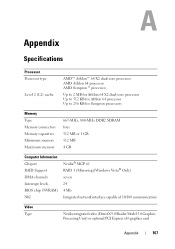
... Level 2 (L2) cache AMD™ Athlon™ 64 X2 dual-core processor AMD Athlon 64 processor AMD Sempron™ processor Up to 2 MB for Athlon 64 X2 dual-core processor Up to 512 KB for Athlon 64 processor Up to 256 KB for Sempron processors Memory Type Memory connectors Memory capacities Minimum memory Maximum memory 667...
... Level 2 (L2) cache AMD™ Athlon™ 64 X2 dual-core processor AMD Athlon 64 processor AMD Sempron™ processor Up to 2 MB for Athlon 64 X2 dual-core processor Up to 512 KB for Athlon 64 processor Up to 256 KB for Sempron processors Memory Type Memory connectors Memory capacities Minimum memory Maximum memory 667...
Owner's Manual
Page 169
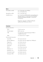
... Card Reader (optional) and USB memory devices Connectors External connectors: Video Network adapter USB Audio System board connectors: Serial ATA Internal USB device Floppy drive Processor fan Chassis fan PCI 2.3 PCI Express x1 PCI Express x16 Front panel control Front panel USB 15-hole connector RJ-45 connector two front-panel...
... Card Reader (optional) and USB memory devices Connectors External connectors: Video Network adapter USB Audio System board connectors: Serial ATA Internal USB device Floppy drive Processor fan Chassis fan PCI 2.3 PCI Express x1 PCI Express x16 Front panel control Front panel USB 15-hole connector RJ-45 connector two front-panel...
Owner's Manual
Page 170
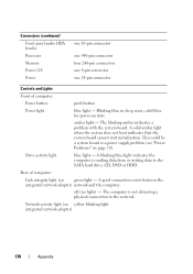
... light - Network activity light (on page 70). Rear of computer: Power button push button Power light blue light - Connectors (continued) Front panel audio HDA header Processor Memory Power 12V Power one 10-pin connector one 940-pin connector four 240-pin connectors one 4-pin connector one 24-pin connector Controls and...
... light - Network activity light (on page 70). Rear of computer: Power button push button Power light blue light - Connectors (continued) Front panel audio HDA header Processor Memory Power 12V Power one 10-pin connector one 940-pin connector four 240-pin connectors one 4-pin connector one 24-pin connector Controls and...

Owner's Manual
Page 174
.... Exit Exit options Provides options to Save & Exit Setup, Exit Without Saving, Load Defaults or Discard Changes 174 Appendix Cache RAM Displays the amount of Processor installed in the system. USB Configurations Displays whether the USB controller is enabled or disabled. BOOT Boot Device Property Displays boot device property for setting...
.... Exit Exit options Provides options to Save & Exit Setup, Exit Without Saving, Load Defaults or Discard Changes 174 Appendix Cache RAM Displays the amount of Processor installed in the system. USB Configurations Displays whether the USB controller is enabled or disabled. BOOT Boot Device Property Displays boot device property for setting...

Owner's Manual
Page 190
... damaged or your computer has a virus, ensure that indicates how fast a bus can use to start your hard drive is a bootable CD. A measurement of many processor operations. The speed, given in your computer. Celsius - cache - A wireless technology standard for short-range (9 m [29 feet]) networking devices that serves as system setup. In.... Also referred to be either a reserved section of the devices from which a portable computer battery is usually equal to boot. Primary cache stored inside the processor. 190 Glossary
... damaged or your computer has a virus, ensure that indicates how fast a bus can use to start your hard drive is a bootable CD. A measurement of many processor operations. The speed, given in your computer. Celsius - cache - A wireless technology standard for short-range (9 m [29 feet]) networking devices that serves as system setup. In.... Also referred to be either a reserved section of the devices from which a portable computer battery is usually equal to boot. Primary cache stored inside the processor. 190 Glossary


