Owner's Manual
Page 7
... Software and Hardware Incompatibilities 91 Restoring Your Operating System 92 Using Microsoft Windows System Restore . . . . 93 Using Dell PC Restore 95 Using the Operating System CD 98 4 Removing and Installing Parts 101 Before You Begin 101 Recommended Tools ... Working Inside Your Computer 102 Removing the Computer Cover 103 Removing the Support Bracket 104 Inside View of Your Computer 106 System Board Components 107 Power Supply DC Connector Pin Assignments . . . . . 109 Memory 112 Memory Installation Guidelines 112 Installing Memory 113 Removing Memory 115 Cards 116 PCI...
... Software and Hardware Incompatibilities 91 Restoring Your Operating System 92 Using Microsoft Windows System Restore . . . . 93 Using Dell PC Restore 95 Using the Operating System CD 98 4 Removing and Installing Parts 101 Before You Begin 101 Recommended Tools ... Working Inside Your Computer 102 Removing the Computer Cover 103 Removing the Support Bracket 104 Inside View of Your Computer 106 System Board Components 107 Power Supply DC Connector Pin Assignments . . . . . 109 Memory 112 Memory Installation Guidelines 112 Installing Memory 113 Removing Memory 115 Cards 116 PCI...
Owner's Manual
Page 8
... a Second Hard Drive (Optional) . . . . . 129 Floppy Drive 131 Media Card Reader 137 CD or DVD Drive 141 Battery 144 Replacing the Battery 144 Power Supply 146 Replacing the Power Supply 146 Processor 148 Removing the Processor 148 Installing the Processor 150 I/O Panel 153 Removing the I/O Panel 153 Installing the I/O Panel 154 Processor Fan 155...
... a Second Hard Drive (Optional) . . . . . 129 Floppy Drive 131 Media Card Reader 137 CD or DVD Drive 141 Battery 144 Replacing the Battery 144 Power Supply 146 Replacing the Power Supply 146 Processor 148 Removing the Processor 148 Installing the Processor 150 I/O Panel 153 Removing the I/O Panel 153 Installing the I/O Panel 154 Processor Fan 155...
Owner's Manual
Page 18
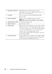
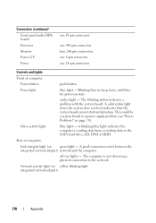
For more information). 2 card slots Access connectors for any installed PCI and PCI Express cards. 3 power supply LED Indicates power availability for attaching a commercially available theft-deterrent device. To use the padlock rings, insert a commercially available ..., see "Back Panel Connectors" on your computer. 4 voltage selector switch For selecting voltage rating. 5 power connector Insert the power cable. 6 padlock rings Padlock rings are for power supply. 1 back panel connectors Plug USB, audio, and other devices into the appropriate connector (see the instructions...
For more information). 2 card slots Access connectors for any installed PCI and PCI Express cards. 3 power supply LED Indicates power availability for attaching a commercially available theft-deterrent device. To use the padlock rings, insert a commercially available ..., see "Back Panel Connectors" on your computer. 4 voltage selector switch For selecting voltage rating. 5 power connector Insert the power cable. 6 padlock rings Padlock rings are for power supply. 1 back panel connectors Plug USB, audio, and other devices into the appropriate connector (see the instructions...

Owner's Manual
Page 106
Inside View of Your Computer CAUTION: Before you begin any of the procedures in this section, follow the safety instructions in the Product Information Guide. 1 2 3 6 4 5 1 power supply 2 hard drive 3 front I/O panel 4 floppy drive or Media 5 CD or DVD drive 6 chassis fan Card Reader (optional) 106 Removing and Installing Parts
Inside View of Your Computer CAUTION: Before you begin any of the procedures in this section, follow the safety instructions in the Product Information Guide. 1 2 3 6 4 5 1 power supply 2 hard drive 3 front I/O panel 4 floppy drive or Media 5 CD or DVD drive 6 chassis fan Card Reader (optional) 106 Removing and Installing Parts
Owner's Manual
Page 109
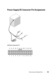
Power Supply DC Connector Pin Assignments DC Power Connector P1 13 14 15 16 17 18 19 20 21 22 23 24 1 2 3 4 5 6 7 8 9 10 11 12 Removing and Installing Parts 109
Power Supply DC Connector Pin Assignments DC Power Connector P1 13 14 15 16 17 18 19 20 21 22 23 24 1 2 3 4 5 6 7 8 9 10 11 12 Removing and Installing Parts 109

Owner's Manual
Page 125
... connector Removing and Installing Parts 125 Connecting Drive Cables When you install a drive, you connect two cables-a DC power cable and a data cable-to connectors labeled "SATA2" or "SATA3" on the system board. 1 2 3 6 4 5 1 power supply 4 floppy drive or Media Card Reader (optional) 2 hard drive 5 CD or DVD drive 3 front I/O panel 6 chassis fan Recommended...
... connector Removing and Installing Parts 125 Connecting Drive Cables When you install a drive, you connect two cables-a DC power cable and a data cable-to connectors labeled "SATA2" or "SATA3" on the system board. 1 2 3 6 4 5 1 power supply 4 floppy drive or Media Card Reader (optional) 2 hard drive 5 CD or DVD drive 3 front I/O panel 6 chassis fan Recommended...
Owner's Manual
Page 146
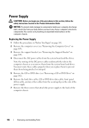
...data cable, front panel ribbon cable, and any other cables from the securing clip on the side of the power supply. 7 Remove the three screws that attach the power supply to components inside your computer, discharge static electricity from your computer's electronic components. You must route these cables... properly when you replace them to prevent them from the system board and the drives. Power Supply CAUTION: Before you begin any of the computer chassis. 146 Removing and Installing Parts You can do so by touching an unpainted ...
...data cable, front panel ribbon cable, and any other cables from the securing clip on the side of the power supply. 7 Remove the three screws that attach the power supply to components inside your computer, discharge static electricity from your computer's electronic components. You must route these cables... properly when you replace them to prevent them from the system board and the drives. Power Supply CAUTION: Before you begin any of the computer chassis. 146 Removing and Installing Parts You can do so by touching an unpainted ...
Owner's Manual
Page 147
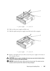
The cables must be properly routed to the back of the system grounding. NOTICE: Route the DC power cables under the chassis tabs. Removing and Installing Parts 147 2 1 1 power supply 2 screws (3) 8 Slide out the power supply and lift it out. 9 Slide the replacement power supply toward the back of the computer. 2 1 1 power supply 2 screws (3) 10 Replace and tighten all screws may cause electrical shock as these screws are a key part of the computer chassis. CAUTION: Failure to replace and tighten all screws that secure the power supply to prevent the cables from being damaged.
The cables must be properly routed to the back of the system grounding. NOTICE: Route the DC power cables under the chassis tabs. Removing and Installing Parts 147 2 1 1 power supply 2 screws (3) 8 Slide out the power supply and lift it out. 9 Slide the replacement power supply toward the back of the computer. 2 1 1 power supply 2 screws (3) 10 Replace and tighten all screws may cause electrical shock as these screws are a key part of the computer chassis. CAUTION: Failure to replace and tighten all screws that secure the power supply to prevent the cables from being damaged.

Owner's Manual
Page 148
...: To prevent static damage to components inside your computer, discharge static electricity from the bracket projection. 148 Removing and Installing Parts 11 Reconnect the DC power cables to the system board and drives. 12 Replace the CD or DVD drive (see "Installing a CD or DVD Drive" on page 143). 13 Secure... cable into the network device and then plug it into the computer. 15 Connect your computer's electronic components. You can do so by running the Dell Diagnostics (see "Removing the Computer Cover" on page 103). 3 Carefully disconnect and move any of the power supply.
...: To prevent static damage to components inside your computer, discharge static electricity from the bracket projection. 148 Removing and Installing Parts 11 Reconnect the DC power cables to the system board and drives. 12 Replace the CD or DVD drive (see "Installing a CD or DVD Drive" on page 143). 13 Secure... cable into the network device and then plug it into the computer. 15 Connect your computer's electronic components. You can do so by running the Dell Diagnostics (see "Removing the Computer Cover" on page 103). 3 Carefully disconnect and move any of the power supply.
Owner's Manual
Page 153
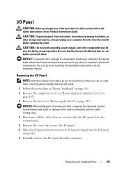
... the bezel (see "Removing the Bezel" on the computer chassis. NOTICE: When sliding the I /O Panel CAUTION: Before you touch them. CAUTION: The heat sink assembly, power supply, and other unexpected injuries, always unplug your computer's electronic components. You can re-route them so that secures the I/O panel. 6 Slide the I/O panel down to...
... the bezel (see "Removing the Bezel" on the computer chassis. NOTICE: When sliding the I /O Panel CAUTION: Before you touch them. CAUTION: The heat sink assembly, power supply, and other unexpected injuries, always unplug your computer's electronic components. You can re-route them so that secures the I/O panel. 6 Slide the I/O panel down to...

Owner's Manual
Page 155
CAUTION: The heat sink assembly, power supply, and other unexpected injuries, always unplug your computer's electronic components. You can do so by moving fan blades, or other components may be very hot ...
CAUTION: The heat sink assembly, power supply, and other unexpected injuries, always unplug your computer's electronic components. You can do so by moving fan blades, or other components may be very hot ...
Owner's Manual
Page 160
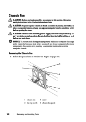
... instructions in "Before You Begin" on the computer chassis. NOTICE: To prevent static damage to cool before opening the cover. CAUTION: The heat sink assembly, power supply, and other unexpected injuries, always unplug your computer's electronic components. Removing the Chassis Fan 1 Follow the procedures in the Product Information Guide. CAUTION: To guard...
... instructions in "Before You Begin" on the computer chassis. NOTICE: To prevent static damage to cool before opening the cover. CAUTION: The heat sink assembly, power supply, and other unexpected injuries, always unplug your computer's electronic components. Removing the Chassis Fan 1 Follow the procedures in the Product Information Guide. CAUTION: To guard...

Owner's Manual
Page 162
... an unpainted metal surface, such as you work, periodically touch an unpainted metal surface to cool before opening the cover. CAUTION: The heat sink assembly, power supply, and other unexpected injuries, always unplug your computer, ground yourself by moving fan blades, or other components may be installed in the same location after...
... an unpainted metal surface, such as you work, periodically touch an unpainted metal surface to cool before opening the cover. CAUTION: The heat sink assembly, power supply, and other unexpected injuries, always unplug your computer, ground yourself by moving fan blades, or other components may be installed in the same location after...
Owner's Manual
Page 170
... connection exists between the integrated network adapter) network and the computer. This could be a system board or a power supply problem (see "Power Problems" on green light - Connectors (continued) Front panel audio HDA header Processor Memory Power 12V Power one 10-pin connector one 940-pin connector four 240-pin connectors one 4-pin connector one 24...
... connection exists between the integrated network adapter) network and the computer. This could be a system board or a power supply problem (see "Power Problems" on green light - Connectors (continued) Front panel audio HDA header Processor Memory Power 12V Power one 10-pin connector one 940-pin connector four 240-pin connectors one 4-pin connector one 24...
Owner's Manual
Page 171
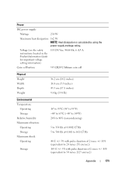
... 250 W Maximum heat dissipation 162 W NOTE: Heat dissipation is calculated by using the power supply wattage rating. Voltage (see the safety instructions located in the Product Information Guide for important voltage setting information) 115/230 Vac, 50/60 Hz, 6 A/3 A Coin ...
... 250 W Maximum heat dissipation 162 W NOTE: Heat dissipation is calculated by using the power supply wattage rating. Voltage (see the safety instructions located in the Product Information Guide for important voltage setting information) 115/230 Vac, 50/60 Hz, 6 A/3 A Coin ...
Owner's Manual
Page 202
...your computer. 202 Glossary Enables Windows programs to shut down your computer. text editor - TPM - U UMA - unified memory allocation - uninterruptible power supply - A UPS keeps a computer running for video cards and controllers that serves as the motherboard. T TAPI - Unless you to operate with ... minutes to create and edit files that contain only text; trusted platform module - system board - A program used when the electrical power fails or drops to underline, change fonts, and so on the computer, do not change the settings for video cards and controllers...
...your computer. 202 Glossary Enables Windows programs to shut down your computer. text editor - TPM - U UMA - unified memory allocation - uninterruptible power supply - A UPS keeps a computer running for video cards and controllers that serves as the motherboard. T TAPI - Unless you to operate with ... minutes to create and edit files that contain only text; trusted platform module - system board - A program used when the electrical power fails or drops to underline, change fonts, and so on the computer, do not change the settings for video cards and controllers...
Owner's Manual
Page 204
...battery. write-protected - WXGA - X XGA - zero insertion force - A special kind of zipped file is 1 ampere of power for 1 hour or 33 W for video cards and controllers that have a filename extension of .exe. A high-capacity floppy ...Control Panel. Z ZIF - wireless local area network. Use write-protection when you want to 100 MB of electrical power. A wireless high-speed data network using access points or wireless routers to 1280 x 800. A popular data compression...Zip - A video standard for 2 hours. watt - You can supply 66 W of current flowing at 1 volt. WLAN -
...battery. write-protected - WXGA - X XGA - zero insertion force - A special kind of zipped file is 1 ampere of power for 1 hour or 33 W for video cards and controllers that have a filename extension of .exe. A high-capacity floppy ...Control Panel. Z ZIF - wireless local area network. Use write-protection when you want to 100 MB of electrical power. A wireless high-speed data network using access points or wireless routers to 1280 x 800. A popular data compression...Zip - A video standard for 2 hours. watt - You can supply 66 W of current flowing at 1 volt. WLAN -


