
FTOS Configuration Guide FTOS 8.4.2.8 E-Series TeraScale
Page 93
... access technologies including ISDN, DSL, and coax cable in the first mile. Ethernet Operations, Administration, and Maintenance (OAM) is that may impact link operation, and monitors the link for those events. 802.3ah | 93 Service Layer OAM: IEEE 802.1ag, Connectivity Fault Management (CFM) 2. Ethernet Local management Interface (MEF-16 E-LMI) Link Layer...
... access technologies including ISDN, DSL, and coax cable in the first mile. Ethernet Operations, Administration, and Maintenance (OAM) is that may impact link operation, and monitors the link for those events. 802.3ah | 93 Service Layer OAM: IEEE 802.1ag, Connectivity Fault Management (CFM) 2. Ethernet Local management Interface (MEF-16 E-LMI) Link Layer...

FTOS Configuration Guide FTOS 8.4.2.8 E-Series TeraScale
Page 446
...dell.com | support.dell.com To test the condition of cables on 10/100/1000 BASE-T modules, use the tdr-cable-test command: Step Command Syntax Command Mode 1 tdr-cable-test gigabitethernet / EXEC Privilege 2 show tdr gigabitethernet / EXEC Privilege Usage To test for cable faults on the GigabitEthernet cable...change. All interfaces have link dampening configured. • Unlike link dampening, link debounce timer does not notify other devices on management interfaces or SONET interfaces. • Link Debounce takes effect only when the operational state of some Layer 2 and Layer 3...
...dell.com | support.dell.com To test the condition of cables on 10/100/1000 BASE-T modules, use the tdr-cable-test command: Step Command Syntax Command Mode 1 tdr-cable-test gigabitethernet / EXEC Privilege 2 show tdr gigabitethernet / EXEC Privilege Usage To test for cable faults on the GigabitEthernet cable...change. All interfaces have link dampening configured. • Unlike link dampening, link debounce timer does not notify other devices on management interfaces or SONET interfaces. • Link Debounce takes effect only when the operational state of some Layer 2 and Layer 3...

FTOS Configuration Guide FTOS 8.4.2.8 E-Series TeraScale
Page 586
...Discovery Protocol-Media Endpoint Discovery (LLDP-MED)-as one or more of the following: repeater, bridge, WLAN Access Point, Router, Telephone, DOCSIS cable device, end station only, or other Indicates the network address of auto-negotiation. FTOS does not currently support this TLV. 127 Maximum Frame...setting of the duplex status and bit rate, and whether the current settings are the result of the management interface. IEEE 802.1 Organizationally Specific TLVs 127 Port-VLAN ID On Dell Force10 systems, indicates the untagged VLAN to which a port belongs 127 Port and Protocol VLAN ID On...
...Discovery Protocol-Media Endpoint Discovery (LLDP-MED)-as one or more of the following: repeater, bridge, WLAN Access Point, Router, Telephone, DOCSIS cable device, end station only, or other Indicates the network address of auto-negotiation. FTOS does not currently support this TLV. 127 Maximum Frame...setting of the duplex status and bit rate, and whether the current settings are the result of the management interface. IEEE 802.1 Organizationally Specific TLVs 127 Port-VLAN ID On Dell Force10 systems, indicates the untagged VLAN to which a port belongs 127 Port and Protocol VLAN ID On...

FTOS Configuration Guide FTOS 8.4.2.8 E-Series TeraScale
Page 1027
... each unit so that each unit to completely boot, and verify that have the same FTOS version. stack-unit priority Connect the units using stacking cables. Power the stack one unit at a time. Common S-Series Stacking Topologies Ring Connection Cascade Connection A B A B A B A B A B A B A...CONFIGURATION EXEC Privilege Stacking S-Series Switches | 1027 Start with the management unit, then the standby, followed by the stack manager, and then power the next unit. Allow each unit to make management unit selection deterministic. A ring topology provides some performance gains and...
... each unit so that each unit to completely boot, and verify that have the same FTOS version. stack-unit priority Connect the units using stacking cables. Power the stack one unit at a time. Common S-Series Stacking Topologies Ring Connection Cascade Connection A B A B A B A B A B A B A...CONFIGURATION EXEC Privilege Stacking S-Series Switches | 1027 Start with the management unit, then the standby, followed by the stack manager, and then power the next unit. Allow each unit to make management unit selection deterministic. A ring topology provides some performance gains and...

FTOS Configuration Guide FTOS 8.4.2.8 E-Series TeraScale
Page 1028
... to a ring by connecting stack-port 2/51 to 0/51; you may rearrange the stacking cables without triggering a unit reset, so long as shown in, in case of a stacking port, module, or cable failure. Removal of only one of the stacking ports, including the topology: Task Display the ...2/51 12 up down 2/52 1/49 12 up up Stacking Cable Redundancy You can connect two units with two stacking cables as the stack manager is never disconnected from the stack. www.dell.com | support.dell.com To display the status of the cables does not trigger a reset. 1028 | Stacking S-Series Switches ...
... to a ring by connecting stack-port 2/51 to 0/51; you may rearrange the stacking cables without triggering a unit reset, so long as shown in, in case of a stacking port, module, or cable failure. Removal of only one of the stacking ports, including the topology: Task Display the ...2/51 12 up down 2/52 1/49 12 up up Stacking Cable Redundancy You can connect two units with two stacking cables as the stack manager is never disconnected from the stack. www.dell.com | support.dell.com To display the status of the cables does not trigger a reset. 1028 | Stacking S-Series Switches ...

FTOS Configuration Guide FTOS 8.4.2.8 E-Series TeraScale
Page 1029
and: • A for the management unit • Bfor the standby management unit • 0 for the stack-number that conflicts with the stack, the stack assigns the first available stack number, as shown in Figure 50-12 ... running and startup configurations with the stack before connecting it becomes the new stack manager and the stack reloads, as show in Figure 50-14 and Figure 50-15. from 0 through 7 - Stacking S-Series Switches | 1029 Stacking Cable Redundancy A B A B A B Stacking Cable Redundancy Stacking 002 LED Status Indicators on an S-Series Stack The stack unit...
and: • A for the management unit • Bfor the standby management unit • 0 for the stack-number that conflicts with the stack, the stack assigns the first available stack number, as shown in Figure 50-12 ... running and startup configurations with the stack before connecting it becomes the new stack manager and the stack reloads, as show in Figure 50-14 and Figure 50-15. from 0 through 7 - Stacking S-Series Switches | 1029 Stacking Cable Redundancy A B A B A B Stacking Cable Redundancy Stacking 002 LED Status Indicators on an S-Series Stack The stack unit...

FTOS Configuration Guide FTOS 8.4.2.8 E-Series TeraScale
Page 1030
...available stack-unit stack-unit renumber number. (OPTIONAL) On the new unit, assign a management priority based on whether you want the new unit to the stack using stacking cables. Adding a Stack Unit with a Conflicting Stack Number-Before STANDALONE BEFORE CONNECTION Standalone#show ...the next available stack-unit number. On the stack, determine the next available stack-unit number, and the management prioritity of the management unit. Stack Info -- Stack Info -- www.dell.com | support.dell.com To manually assign a new unit a position in the stack: Step 1 2 3 4 5 6 ...
...available stack-unit stack-unit renumber number. (OPTIONAL) On the new unit, assign a management priority based on whether you want the new unit to the stack using stacking cables. Adding a Stack Unit with a Conflicting Stack Number-Before STANDALONE BEFORE CONNECTION Standalone#show ...the next available stack-unit number. On the stack, determine the next available stack-unit number, and the management prioritity of the management unit. Stack Info -- Stack Info -- www.dell.com | support.dell.com To manually assign a new unit a position in the stack: Step 1 2 3 4 5 6 ...

FTOS Configuration Guide FTOS 8.4.2.8 E-Series TeraScale
Page 1032
www.dell.com | support.dell.com Figure 50-15. You may... chapter. 1032 | Stacking S-Series Switches To remove a stack member from the stack, disconnect the stacking cables from an S-Series Stack The running-configuration and startup-configuration are synchronized on all stack units. A stack...presentGoing for reboot. Stack Info -- Unit UnitType Status ReqTyp CurTyp Version Ports 0 Member type mismatch S25N S50V 7.8.1.0 52 1 Management online S50N S50N 7.8.1.0 52 2 Standby online S50V S50V 7.8.1.0 52 3 Member not present 4 Member not present 5 Member not...
www.dell.com | support.dell.com Figure 50-15. You may... chapter. 1032 | Stacking S-Series Switches To remove a stack member from the stack, disconnect the stacking cables from an S-Series Stack The running-configuration and startup-configuration are synchronized on all stack units. A stack...presentGoing for reboot. Stack Info -- Unit UnitType Status ReqTyp CurTyp Version Ports 0 Member type mismatch S25N S50V 7.8.1.0 52 1 Management online S50N S50N 7.8.1.0 52 2 Standby online S50V S50V 7.8.1.0 52 3 Member not present 4 Member not present 5 Member not...

FTOS Configuration Guide FTOS 8.4.2.8 E-Series TeraScale
Page 1034
... is no unit numbering conflict, the stack members retain their previous unit numbers. Unit UnitType Status ReqTyp CurTyp Version Ports 0 Standby online S50V S50V 7.8.1.0 52 1 Management online S50N S50N 7.8.1.0 52 2 Member not present S50V 3 Member not present 4 Member not present 5 Member not present 6 Member not present 7 Member not present Merge ... 2/1-48 Stack#show system brief Stack MAC : 00:01:e8:d5:ef:81 -- To merge two stacks, connect one stack to the other using stacking cables. www.dell.com | support.dell.com Figure 50-17. Stack Info --
... is no unit numbering conflict, the stack members retain their previous unit numbers. Unit UnitType Status ReqTyp CurTyp Version Ports 0 Standby online S50V S50V 7.8.1.0 52 1 Management online S50N S50N 7.8.1.0 52 2 Member not present S50V 3 Member not present 4 Member not present 5 Member not present 6 Member not present 7 Member not present Merge ... 2/1-48 Stack#show system brief Stack MAC : 00:01:e8:d5:ef:81 -- To merge two stacks, connect one stack to the other using stacking cables. www.dell.com | support.dell.com Figure 50-17. Stack Info --

E600 TeraScale Installation Guide
Page 9
... as hot air vents or direct sunlight. 3 The site is away from a filtered intake vent on the bottom front side of the chassis to cables, and maintenance access. Equipment Rack and Cabinet Requirements 1 Ensure that the rack has adequate space in the front, rear, and sides after the system...begin, make sure that the minimum air flow is 750 cubic feet per minute (CFM), this requires a minimum of 3 inches between the doors and the cable management system when the cabinet front doors are closed, and a minimum of 3 inches between the chassis rear and the rear of the cabinet. 2 Site Preparation...
... as hot air vents or direct sunlight. 3 The site is away from a filtered intake vent on the bottom front side of the chassis to cables, and maintenance access. Equipment Rack and Cabinet Requirements 1 Ensure that the rack has adequate space in the front, rear, and sides after the system...begin, make sure that the minimum air flow is 750 cubic feet per minute (CFM), this requires a minimum of 3 inches between the doors and the cable management system when the cabinet front doors are closed, and a minimum of 3 inches between the chassis rear and the rear of the cabinet. 2 Site Preparation...
E600 TeraScale Installation Guide
Page 13
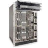
... Installation Process To install the E600i system, Dell Force10 recommends that you perform the installation procedures in the following order: Step 1 2 3 Task Prepare the site Unpack the chassis and components Mount the chassis 4 Install components: • Fan tray • AC Power Supply or DC PEMs (including power cables) 5 Install card components: • RPM(s) and...
... Installation Process To install the E600i system, Dell Force10 recommends that you perform the installation procedures in the following order: Step 1 2 3 Task Prepare the site Unpack the chassis and components Mount the chassis 4 Install components: • Fan tray • AC Power Supply or DC PEMs (including power cables) 5 Install card components: • RPM(s) and...

E600 TeraScale Installation Guide
Page 65
...; DC Power Entry Module Requirement • Agency Compliance Chassis Physical Design Parameter Specifications Height 28 inches (71.1 cm) Width 17.4 inches (44.2 cm) Depth (without cable management system) 21.5 inches (54.6 cm) Chassis weight with factory-installed components (backplane and air filter) 81 pounds (36.7 kg) Weight fully loaded (backplane, air filter...
...; DC Power Entry Module Requirement • Agency Compliance Chassis Physical Design Parameter Specifications Height 28 inches (71.1 cm) Width 17.4 inches (44.2 cm) Depth (without cable management system) 21.5 inches (54.6 cm) Chassis weight with factory-installed components (backplane and air filter) 81 pounds (36.7 kg) Weight fully loaded (backplane, air filter...

E600i System Installation Guide
Page 12
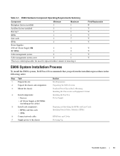
... Requirements Component Minimum Cable management system 0 Cable management system cover 0 Maximum 1 1 Field-Replaceable Y Y Install the E600i Chassis To install the E600i system: Step Task 1 Prepare the installation site. 2 Unpack the chassis and components 3 Mount the chassis in a rack or cabinet. 4 Install the fan tray. 5 Install the ... in a Cabinet Install the Fan Tray Install the AC Power Supply Units Install the DC PEMs Install RPMs, Line Cards, and SFMs RPM Ports and Cables 12 | The E600i System www.dell.com | support.dell.com Table 2-1.
... Requirements Component Minimum Cable management system 0 Cable management system cover 0 Maximum 1 1 Field-Replaceable Y Y Install the E600i Chassis To install the E600i system: Step Task 1 Prepare the installation site. 2 Unpack the chassis and components 3 Mount the chassis in a rack or cabinet. 4 Install the fan tray. 5 Install the ... in a Cabinet Install the Fan Tray Install the AC Power Supply Units Install the DC PEMs Install RPMs, Line Cards, and SFMs RPM Ports and Cables 12 | The E600i System www.dell.com | support.dell.com Table 2-1.

E600i System Installation Guide
Page 13
... or cabinet so that the minimum air flow is 750 cubic feet per minute (CFM), this requires a minimum of 3 inches between the doors and the cable management system when the cabinet front doors are closed, and a minimum of 3 inches between the chassis rear and the rear of the chassis to an exhaust... air vents or direct sunlight. 3 The site is away from a filtered intake vent on the bottom front side of the cabinet. Connect the system to cables, and maintenance access.
... or cabinet so that the minimum air flow is 750 cubic feet per minute (CFM), this requires a minimum of 3 inches between the doors and the cable management system when the cabinet front doors are closed, and a minimum of 3 inches between the chassis rear and the rear of the chassis to an exhaust... air vents or direct sunlight. 3 The site is away from a filtered intake vent on the bottom front side of the cabinet. Connect the system to cables, and maintenance access.

E600i System Installation Guide
Page 55
...; DC Power Entry Module Requirement • Agency Compliance Chassis Physical Design Parameter Specifications Height 28 inches (71.1 cm) Width 17.4 inches (44.2 cm) Depth (without cable management system) 21.5 inches (54.6 cm) Chassis weight with factory-installed components (backplane and air filter) 81 pounds (36.7 kg) Weight fully loaded (backplane, air filter...
...; DC Power Entry Module Requirement • Agency Compliance Chassis Physical Design Parameter Specifications Height 28 inches (71.1 cm) Width 17.4 inches (44.2 cm) Depth (without cable management system) 21.5 inches (54.6 cm) Chassis weight with factory-installed components (backplane and air filter) 81 pounds (36.7 kg) Weight fully loaded (backplane, air filter...

Quick Start Guide
Page 30
E300 Specifications E300 Chassis Physical Design Parameter E1200i AC Specifications Height 14 inches (35.6 cm) Width 17.4 inches (44.2 cm) Depth (without cable management system) 24 inches (61 cm) Chassis weight with factory-installed 90 pounds (approx.) (41 kg) components (backplane and air filter) Weight fully loaded (backplane, air ...
E300 Specifications E300 Chassis Physical Design Parameter E1200i AC Specifications Height 14 inches (35.6 cm) Width 17.4 inches (44.2 cm) Depth (without cable management system) 24 inches (61 cm) Chassis weight with factory-installed 90 pounds (approx.) (41 kg) components (backplane and air filter) Weight fully loaded (backplane, air ...

Quick Start Guide
Page 32
... (16,065 BTU/hour) 200/240 VAC powered: 4250W (14,500 BTU/hour) DC powered: 2800W (9600 BTU/hour) E600i TeraScale Environmental Parameters Parameter Specifications Operating Temperature 32° to 104°F (0° to 40°C) Maximum altitude No performance degradation...572 meters) Relative Humidity 5 to system configuration and number of line cards. Parameter Specifications Width 17.4 inches (44.2 cm) Depth (without cable management system) 21.5 inches (54.6 cm) Chassis weight with factory-installed 81 pounds (36.7 kg) components (backplane and air filter) Weight fully...
... (16,065 BTU/hour) 200/240 VAC powered: 4250W (14,500 BTU/hour) DC powered: 2800W (9600 BTU/hour) E600i TeraScale Environmental Parameters Parameter Specifications Operating Temperature 32° to 104°F (0° to 40°C) Maximum altitude No performance degradation...572 meters) Relative Humidity 5 to system configuration and number of line cards. Parameter Specifications Width 17.4 inches (44.2 cm) Depth (without cable management system) 21.5 inches (54.6 cm) Chassis weight with factory-installed 81 pounds (36.7 kg) components (backplane and air filter) Weight fully...

Quick Start Guide
Page 33
... @ 220/240 VAC Maximum Power Consumption 3,422 W at 100/120 VAC 3,156 W at 200/240 VAC E600i ExaScale Chassis Physical Design Parameter Specifications Height 28 inches (71.1 cm) Width 17.4 inches (44.2 cm) Depth (without cable management system) 21.5 inches (54.6 cm) Chassis weight with factory-installed 81 pounds (36.7 kg) components (backplane...
... @ 220/240 VAC Maximum Power Consumption 3,422 W at 100/120 VAC 3,156 W at 200/240 VAC E600i ExaScale Chassis Physical Design Parameter Specifications Height 28 inches (71.1 cm) Width 17.4 inches (44.2 cm) Depth (without cable management system) 21.5 inches (54.6 cm) Chassis weight with factory-installed 81 pounds (36.7 kg) components (backplane...

Quick Start Guide
Page 35
... inches (106.68 cm) 36.75 inches (93.35 cm) Width 17.40 inches (44.20 cm) 17.40 inches (44.20 cm) Depth (without cable management system) 22.25 inches (56.51 cm) 21.25 inches (53.98 cm) Chassis weight with factory- 139 pounds (approx.) installed components (63.05kg) (backplane...
... inches (106.68 cm) 36.75 inches (93.35 cm) Width 17.40 inches (44.20 cm) 17.40 inches (44.20 cm) Depth (without cable management system) 22.25 inches (56.51 cm) 21.25 inches (53.98 cm) Chassis weight with factory- 139 pounds (approx.) installed components (63.05kg) (backplane...

Quick Start Guide
Page 36
... inches (106.68 cm) 36.75 inches (93.35 cm) Width 17.40 inches (44.20 cm) 17.40 inches (44.20 cm) Depth (without cable management system) 22.25 inches (56.51 cm) 21.25 inches (53.98 cm) Chassis weight with factory- 139 pounds (approx.) installed components (63.05kg) (backplane...
... inches (106.68 cm) 36.75 inches (93.35 cm) Width 17.40 inches (44.20 cm) 17.40 inches (44.20 cm) Depth (without cable management system) 22.25 inches (56.51 cm) 21.25 inches (53.98 cm) Chassis weight with factory- 139 pounds (approx.) installed components (63.05kg) (backplane...


