Force10 Networks E1200i - Dell
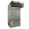
Force10 Networks E1200i
View Results Below
Free Dell Force10 E1200i manuals!
Problems with Dell Force10 E1200i?
Ask a Question
Free Dell Force10 E1200i manuals!
Problems with Dell Force10 E1200i?
Ask a Question
Related Manual Pages


Similar Questions

Poweredge 1955 How To Connect All The Network Cable
(Posted by caneliza 10 years ago)
How To Tell If Network Card Is Bad Dell Poweredge 2950
(Posted by meekswin 10 years ago)

Network Controller And Sm Bus Controller Missing-dell Vostro 1550
After Reinstalling The Win 7 The Network And Sm Bus Controller Are Missing From My Dell Vostro 1550 ...
After Reinstalling The Win 7 The Network And Sm Bus Controller Are Missing From My Dell Vostro 1550 ...
(Posted by MANOHARbhatia 11 years ago)