
E1200i ExaScale Installation Guide
Page 3
... 15 Rack Mounting 16 Cabinet Placement 16 Power 16 Fans and Airflow 17 Storing Components 17 4 Installing the AC Chassis Unpacking the E1200 System 19 Installing the Equipment Rack Shelf Bar 20 Standard Front Chassis Mounting 20 Installing the Chassis into an Equipment Cabinet 22 5 ...Installing the DC Chassis Unpacking the E1200 System 23 Installing the Equipment Rack Shelf Bar 24 Standard Front Chassis Mounting 24 Installing the Chassis into an Equipment Cabinet 26 6 ...
... 15 Rack Mounting 16 Cabinet Placement 16 Power 16 Fans and Airflow 17 Storing Components 17 4 Installing the AC Chassis Unpacking the E1200 System 19 Installing the Equipment Rack Shelf Bar 20 Standard Front Chassis Mounting 20 Installing the Chassis into an Equipment Cabinet 22 5 ...Installing the DC Chassis Unpacking the E1200 System 23 Installing the Equipment Rack Shelf Bar 24 Standard Front Chassis Mounting 24 Installing the Chassis into an Equipment Cabinet 26 6 ...

E1200i ExaScale Installation Guide
Page 7
... result in empty slots to laser radiation and do not stare into open apertures. Read this guide before servicing. E1200i systems run Dell Force10 OS (FTOS™) software. After you complete the hardware installation process and power up this guide. Caution Warning ...operational information. About This Guide | 7 Information Symbols and Warnings Table 1-1 defines the information symbols used throughout this equipment. The E1200 system is connected. Blanks are required in injury. Information Symbols Symbol Warning Note Description This symbol informs you that could result ...
... result in empty slots to laser radiation and do not stare into open apertures. Read this guide before servicing. E1200i systems run Dell Force10 OS (FTOS™) software. After you complete the hardware installation process and power up this guide. Caution Warning ...operational information. About This Guide | 7 Information Symbols and Warnings Table 1-1 defines the information symbols used throughout this equipment. The E1200 system is connected. Blanks are required in injury. Information Symbols Symbol Warning Note Description This symbol informs you that could result ...

E1200i ExaScale Installation Guide
Page 8
See Chapter 3, Site Preparation for more information about the E1200 system, refer to the following documents: • FTOS Configuration Guide • FTOS Command Reference • FTOS Release Notes for the E-Series ExaScale 8 | About This Guide Related Publications For more cautions. The power cord plugs must be secured to the power inlet using the provided brackets. www.dell.com | support.dell.com WARNING: Leakage Current (High Touch Current) in AC-powered systems: AC power cords are secured to the building outlets by the qualified chassis installer or a qualified electrician.
See Chapter 3, Site Preparation for more information about the E1200 system, refer to the following documents: • FTOS Configuration Guide • FTOS Command Reference • FTOS Release Notes for the E-Series ExaScale 8 | About This Guide Related Publications For more cautions. The power cord plugs must be secured to the power inlet using the provided brackets. www.dell.com | support.dell.com WARNING: Leakage Current (High Touch Current) in AC-powered systems: AC power cords are secured to the building outlets by the qualified chassis installer or a qualified electrician.

E1200i ExaScale Installation Guide
Page 9
... memory card and two USB ports that can be used to the forwarding information tables on each other, increasing reliability. 2 The E1200 System The Dell Force10 E1200 system is the core for routing and control operations; The FPC accepts packets, feeds packets to Chapter 13, Using a Flash Memory... traffic destined for the E1200i terminates on the RPM and directed to copy and store system boot, software images, and configuration files. Software processes, such as Telnet, SNMP, CLI, Layer 2, and Layer 3 functions, are built on the RPM. Operating the E1200 system with the RPM ...
... memory card and two USB ports that can be used to the forwarding information tables on each other, increasing reliability. 2 The E1200 System The Dell Force10 E1200 system is the core for routing and control operations; The FPC accepts packets, feeds packets to Chapter 13, Using a Flash Memory... traffic destined for the E1200i terminates on the RPM and directed to copy and store system boot, software images, and configuration files. Software processes, such as Telnet, SNMP, CLI, Layer 2, and Layer 3 functions, are built on the RPM. Operating the E1200 system with the RPM ...

E1200i ExaScale Installation Guide
Page 11
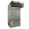
Figure 2-2. E1200 AC Chassis Rear View Installed Fan Tray Locking Screw Empty Fan Tray (with self-closing door) Ground Connection The E1200 System | 11
Figure 2-2. E1200 AC Chassis Rear View Installed Fan Tray Locking Screw Empty Fan Tray (with self-closing door) Ground Connection The E1200 System | 11

E1200i ExaScale Installation Guide
Page 13
E1200 Hardware Component Operating Requirements Summary Component Backplane (factory installed) Air filter (factory installed) Fan trays RPMs Line cards SFM3s AC Power Supply DC Power Supply Cable management system Cable management system cover Minimum 1 1 2 1 1 8 3 (in a shelf) 1 0 0 Maximum 1 1 2 2 14 10 6 2 1 1 Field-Replaceable N Y Y Y Y Y Y Y Y Y The E1200 System | 13 Figure 2-4. E1200 DC Chassis Rear View Installed Fan Tray Locking Screw Empty Fan Tray (with self-closing door) Ground Connection Table 2-1.
E1200 Hardware Component Operating Requirements Summary Component Backplane (factory installed) Air filter (factory installed) Fan trays RPMs Line cards SFM3s AC Power Supply DC Power Supply Cable management system Cable management system cover Minimum 1 1 2 1 1 8 3 (in a shelf) 1 0 0 Maximum 1 1 2 2 14 10 6 2 1 1 Field-Replaceable N Y Y Y Y Y Y Y Y Y The E1200 System | 13 Figure 2-4. E1200 DC Chassis Rear View Installed Fan Tray Locking Screw Empty Fan Tray (with self-closing door) Ground Connection Table 2-1.

E1200i ExaScale Installation Guide
Page 14
www.dell.com | support.dell.com To install the E1200 system: Step Task 1 Prepare the site 2 Unpack the AC chassis and components or Unpack the DC chassis and components 3 Mount the AC chassis or Section Site Preparation Unpacking the E1200 System Unpacking the E1200 System Standard Front Chassis Mounting... management system. DC 10 Initial boot The initial boot operation automatically brings up the system to continue the boot process. 14 | The E1200 System Refer to Chapter A, System Boot for instructions to the runtime CLI. To interrupt the automatic boot process, issue a break key ...
www.dell.com | support.dell.com To install the E1200 system: Step Task 1 Prepare the site 2 Unpack the AC chassis and components or Unpack the DC chassis and components 3 Mount the AC chassis or Section Site Preparation Unpacking the E1200 System Unpacking the E1200 System Standard Front Chassis Mounting... management system. DC 10 Initial boot The initial boot operation automatically brings up the system to continue the boot process. 14 | The E1200 System Refer to Chapter A, System Boot for instructions to the runtime CLI. To interrupt the automatic boot process, issue a break key ...

E1200i ExaScale Installation Guide
Page 15
...a rack with adequate space in the front and rear, and sides of the unit for ventilation. Site Preparation | 15 Connect the E1200 to the appropriate branch circuit protection as hot air vents or direct sunlight. • Away from sources of power disconnect must be ... Site Selection Criteria • Rack Mounting • Cabinet Placement • Power • Fans and Airflow • Storing Components For complete E1200 System Specifications, refer to cables, and maintenance access. Site Selection Criteria Before you begin the installation process, make sure that there is enough ...
...a rack with adequate space in the front and rear, and sides of the unit for ventilation. Site Preparation | 15 Connect the E1200 to the appropriate branch circuit protection as hot air vents or direct sunlight. • Away from sources of power disconnect must be ... Site Selection Criteria • Rack Mounting • Cabinet Placement • Power • Fans and Airflow • Storing Components For complete E1200 System Specifications, refer to cables, and maintenance access. Site Selection Criteria Before you begin the installation process, make sure that there is enough ...

E1200i ExaScale Installation Guide
Page 16
...internal components or make sure the rack is grounded to lift or move the chassis without the use of power supply module installed. www.dell.com | support.dell.com • Ensure that the equipment is 750 cubic feet per minute (CFM). • Minimum of 3 inches between the closed ... 5) or 1 DC PEM to 400 pounds. The unpacked chassis and pallet weigh approximately 200 pounds. Rack Mounting When you will cause chassis damage. Power The E1200 requires 3 AC Power Supplies in the other shelf) or a second 2 DC Power Entry Module (2 total) CAUTION: You cannot power the system with the ...
...internal components or make sure the rack is grounded to lift or move the chassis without the use of power supply module installed. www.dell.com | support.dell.com • Ensure that the equipment is 750 cubic feet per minute (CFM). • Minimum of 3 inches between the closed ... 5) or 1 DC PEM to 400 pounds. The unpacked chassis and pallet weigh approximately 200 pounds. Rack Mounting When you will cause chassis damage. Power The E1200 requires 3 AC Power Supplies in the other shelf) or a second 2 DC Power Entry Module (2 total) CAUTION: You cannot power the system with the ...

E1200i ExaScale Installation Guide
Page 17
...inches in the rear are available to operate. they prevent unauthorized access to 104° F (40° C). WARNING: Make your E1200 system and components right away, properly store components and all times. WARNING: Disconnect all power to the building outlets by the chassis installer...on thermal output and other power related numbers. WARNING: The E1200i AC Chassis is not correctly grounded, excessive electromagnetic emission may damage the components and the chassis backplane. WARNING: Never operate the E1200 system with blank panels. Place the modules in its original ...
...inches in the rear are available to operate. they prevent unauthorized access to 104° F (40° C). WARNING: Make your E1200 system and components right away, properly store components and all times. WARNING: Disconnect all power to the building outlets by the chassis installer...on thermal output and other power related numbers. WARNING: The E1200i AC Chassis is not correctly grounded, excessive electromagnetic emission may damage the components and the chassis backplane. WARNING: Never operate the E1200 system with blank panels. Place the modules in its original ...

E1200i ExaScale Installation Guide
Page 19
...This chapter provides instructions to rack mount your safety: This unit should be mounted at the bottom of the rack. CAUTION: Lift the E1200 chassis only with stabilizing devices, install the stabilizers before you install any other component (fan trays, power supplies, line cards, RPMs, ...an ESD-preventative wrist or foot-heal ground strap when handling RPMs, SFM3s, or line cards. The following sections: • Unpacking the E1200 System • Installing the Equipment Rack Shelf Bar • Standard Front Chassis Mounting • Installing the Chassis into the rack before mounting ...
...This chapter provides instructions to rack mount your safety: This unit should be mounted at the bottom of the rack. CAUTION: Lift the E1200 chassis only with stabilizing devices, install the stabilizers before you install any other component (fan trays, power supplies, line cards, RPMs, ...an ESD-preventative wrist or foot-heal ground strap when handling RPMs, SFM3s, or line cards. The following sections: • Unpacking the E1200 System • Installing the Equipment Rack Shelf Bar • Standard Front Chassis Mounting • Installing the Chassis into the rack before mounting ...

E1200i ExaScale Installation Guide
Page 20
... Task 1 Determine the chassis mounting location in a rack, you to the equipment rack brackets using the mounting screws provided by the manufacturer. Figure 4-1. www.dell.com | support.dell.com Installing the Equipment Rack Shelf Bar The rack shelf bar (Figure 4-1) enables you must be mounted at the bottom of the rack. •... bar with the arrows pointing upward. Standard Front Chassis Mounting WARNING: To prevent bodily injury when mounting or servicing this unit in the rack. The E1200 system must take special precautions to the floor.
... Task 1 Determine the chassis mounting location in a rack, you to the equipment rack brackets using the mounting screws provided by the manufacturer. Figure 4-1. www.dell.com | support.dell.com Installing the Equipment Rack Shelf Bar The rack shelf bar (Figure 4-1) enables you must be mounted at the bottom of the rack. •... bar with the arrows pointing upward. Standard Front Chassis Mounting WARNING: To prevent bodily injury when mounting or servicing this unit in the rack. The E1200 system must take special precautions to the floor.

E1200i ExaScale Installation Guide
Page 21
...shelf bar. 4 Insert rack mounting screws in the holes that you install and operate the E1200 system in the rack. Installing the AC Chassis | 21 Tighten the screws. Install the E1200 system after you are not obscured by the metal chassis shipping cover. Figure 4-2. See Figure... mit Stabilisierungszubehör geliefert, sind zuerst die Stabilisatoren zu installieren, bevor Sie die Einheit im Gestell anbringen oder sie warten. NOTE: Dell Force10 recommends that are center or rear-mounting the chassis in a 19-inch rack, adjust the chassis rack mounting brackets to secure the chassis...
...shelf bar. 4 Insert rack mounting screws in the holes that you install and operate the E1200 system in the rack. Installing the AC Chassis | 21 Tighten the screws. Install the E1200 system after you are not obscured by the metal chassis shipping cover. Figure 4-2. See Figure... mit Stabilisierungszubehör geliefert, sind zuerst die Stabilisatoren zu installieren, bevor Sie die Einheit im Gestell anbringen oder sie warten. NOTE: Dell Force10 recommends that are center or rear-mounting the chassis in a 19-inch rack, adjust the chassis rack mounting brackets to secure the chassis...

E1200i ExaScale Installation Guide
Page 22
To install the chassis into an Equipment Cabinet Install the E1200 system after you secure the rack shelf bar. www.dell.com | support.dell.com Installing the Chassis into an equipment cabinet: Step Task 1 Install the equipment rack shelf bar. 2 Adjust the chassis mounting brackets to the desired front-...
To install the chassis into an Equipment Cabinet Install the E1200 system after you secure the rack shelf bar. www.dell.com | support.dell.com Installing the Chassis into an equipment cabinet: Step Task 1 Install the equipment rack shelf bar. 2 Adjust the chassis mounting brackets to the desired front-...

E1200i ExaScale Installation Guide
Page 23
It contains the following sections: • Unpacking the E1200 System • Standard Front Chassis Mounting • Installing the Chassis into a standard 19-inch or 23-inch equipment rack. Do not attempt to the internal ... DC Chassis This chapter provides instructions to 400 pounds. WARNING: The E1200 DC shipping containers each weigh up to rack mount your E1200 system into an Equipment Cabinet Unpacking the E1200 System The E1200 DC system and components are mishandled. CAUTION: Lift the E1200 chassis only with Front Shipping cover. WARNING: Pour ce qui est...
It contains the following sections: • Unpacking the E1200 System • Standard Front Chassis Mounting • Installing the Chassis into a standard 19-inch or 23-inch equipment rack. Do not attempt to the internal ... DC Chassis This chapter provides instructions to 400 pounds. WARNING: The E1200 DC shipping containers each weigh up to rack mount your E1200 system into an Equipment Cabinet Unpacking the E1200 System The E1200 DC system and components are mishandled. CAUTION: Lift the E1200 chassis only with Front Shipping cover. WARNING: Pour ce qui est...

E1200i ExaScale Installation Guide
Page 24
The E1200 system must take special precautions to ensure that is permanently secured to the equipment rack brackets using the mounting screws provided by the manufacturer. The ...;parer l'unité en casier. 24 | Installing the DC Chassis The smooth side of the bar should be mounted in the rack. Figure 5-1. www.dell.com | support.dell.com Installing the Equipment Rack Shelf Bar The rack shelf bar (Figure 5-1) enables you must be mounted at the bottom of the rack. •...
The E1200 system must take special precautions to ensure that is permanently secured to the equipment rack brackets using the mounting screws provided by the manufacturer. The ...;parer l'unité en casier. 24 | Installing the DC Chassis The smooth side of the bar should be mounted in the rack. Figure 5-1. www.dell.com | support.dell.com Installing the Equipment Rack Shelf Bar The rack shelf bar (Figure 5-1) enables you must be mounted at the bottom of the rack. •...

E1200i ExaScale Installation Guide
Page 25
...5-2) WARNING: Do not remove the Front shipping Cover during the initial installation process. Installing the DC Chassis | 25 Install the E1200 system after you center- WARNING: Zur Vermeidung von Körperverletzung beim Anbringen oder Warten dieser Einheit in einem zum Teil gef&#... Stabilisierungszubehör geliefert, sind zuerst die Stabilisatoren zu installieren, bevor Sie die Einheit im Gestell anbringen oder sie warten. NOTE: Dell Force10 recommends that are not obscured by the metal chassis shipping cover. See Figure 5-2. 5 Loosen and remove the screws that secure the...
...5-2) WARNING: Do not remove the Front shipping Cover during the initial installation process. Installing the DC Chassis | 25 Install the E1200 system after you center- WARNING: Zur Vermeidung von Körperverletzung beim Anbringen oder Warten dieser Einheit in einem zum Teil gef&#... Stabilisierungszubehör geliefert, sind zuerst die Stabilisatoren zu installieren, bevor Sie die Einheit im Gestell anbringen oder sie warten. NOTE: Dell Force10 recommends that are not obscured by the metal chassis shipping cover. See Figure 5-2. 5 Loosen and remove the screws that secure the...

E1200i ExaScale Installation Guide
Page 26
... the screws. 5 Loosen and remove the screws attaching the chassis shipping cover. To install the chassis into an Equipment Cabinet Install the E1200 system after you secure the rack shelf bar. Remove the shipping cover. 6 Insert the remaining mounting screws and tighten to secure the ...chassis in the lower half of the unit for proper ventilation, access to cables, and access for complete requirements. www.dell.com | support.dell.com Installing the Chassis into an equipment cabinet: Step Task 1 Install the equipment rack shelf bar. 2 Adjust the chassis mounting ...
... the screws. 5 Loosen and remove the screws attaching the chassis shipping cover. To install the chassis into an Equipment Cabinet Install the E1200 system after you secure the rack shelf bar. Remove the shipping cover. 6 Insert the remaining mounting screws and tighten to secure the ...chassis in the lower half of the unit for proper ventilation, access to cables, and access for complete requirements. www.dell.com | support.dell.com Installing the Chassis into an equipment cabinet: Step Task 1 Install the equipment rack shelf bar. 2 Adjust the chassis mounting ...
E1200i ExaScale Installation Guide
Page 29
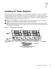
...if the three power supplies are installing only three power supplies, they must be in Figure 7-1. NOTE: The On/Standby switch disconnects power to operate. E1200i AC Power Supply Shelf Power Supplies On/Standby Switch AC-Cord Retainer Safety Cover AC-0 AC-1 AC-2 AC-3 AC-4 AC-5 AC-0 AC-3 AC-1... AC power supplies in the same row. Locking Screw This retainer must install the AC-cord retainer over all 6 AC power supplies slots. The E1200 chassis contains 6 AC power supply slots, as shown in place during normal operation. For full redundancy use 6 power supplies so that if one ...
...if the three power supplies are installing only three power supplies, they must be in Figure 7-1. NOTE: The On/Standby switch disconnects power to operate. E1200i AC Power Supply Shelf Power Supplies On/Standby Switch AC-Cord Retainer Safety Cover AC-0 AC-1 AC-2 AC-3 AC-4 AC-5 AC-0 AC-3 AC-1... AC power supplies in the same row. Locking Screw This retainer must install the AC-cord retainer over all 6 AC power supplies slots. The E1200 chassis contains 6 AC power supply slots, as shown in place during normal operation. For full redundancy use 6 power supplies so that if one ...
E1200i ExaScale Installation Guide
Page 35
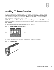
... SF4L-SFMC SF4L-SFMC Force10 Networks Force10 Networks Force10 Networks Force10 Networks Force10 Networks Force10 Networks Force10 Networks Force10 Networks Force10 Networks online fail online fail online fail online fail online fail online fail online fail online fail online fail online fail PEM 1 FN00100lp The DC PEM shown in Figure 8-2 is used in both the E1200 and E1200i DC chassis. Connect...
... SF4L-SFMC SF4L-SFMC Force10 Networks Force10 Networks Force10 Networks Force10 Networks Force10 Networks Force10 Networks Force10 Networks Force10 Networks Force10 Networks online fail online fail online fail online fail online fail online fail online fail online fail online fail online fail PEM 1 FN00100lp The DC PEM shown in Figure 8-2 is used in both the E1200 and E1200i DC chassis. Connect...