
Hardware Reference
Page 2
... identify, products or services of technical data contained in this document may contain "open source" software covered by Brocade. Brocade reserves the right to make changes to this document may require an export license from the information contained in this is included in other brands, products, or service names are trademarks of the programming source code, please visit http://www.brocade.com/support/oscd. All other...
... identify, products or services of technical data contained in this document may contain "open source" software covered by Brocade. Brocade reserves the right to make changes to this document may require an export license from the information contained in this is included in other brands, products, or service names are trademarks of the programming source code, please visit http://www.brocade.com/support/oscd. All other...
Hardware Reference
Page 3
...Field Replaceable Units 3 Managing the Brocade 5000 3 Supported Features 4 Ports On Demand 4 Chapter 2 Installing and Configuring the Brocade 5000 Items Included with the Brocade 5000 5 Installation and Safety Considerations 5 Setting Up the Switch Using Mounting Ears 6 Setting Up the Brocade 5000 as a Standalone Unit 7 Configuring the Brocade 5000 7 Setting the Switch Date and Time 12 Synchronizing Local Time with an External Source 12 Correcting the Time Zone of a Switch 13 Recommendations for Cable Management 13 Brocade 5000 Hardware Reference Manual iii Publication Number...
...Field Replaceable Units 3 Managing the Brocade 5000 3 Supported Features 4 Ports On Demand 4 Chapter 2 Installing and Configuring the Brocade 5000 Items Included with the Brocade 5000 5 Installation and Safety Considerations 5 Setting Up the Switch Using Mounting Ears 6 Setting Up the Brocade 5000 as a Standalone Unit 7 Configuring the Brocade 5000 7 Setting the Switch Date and Time 12 Synchronizing Local Time with an External Source 12 Correcting the Time Zone of a Switch 13 Recommendations for Cable Management 13 Brocade 5000 Hardware Reference Manual iii Publication Number...

Hardware Reference
Page 7
... An attention alerts you might find helpful. NOTES, ATTENTIONS, CAUTIONS, AND DANGERS The following related documentation is provided on the Brocade Documentation CD-ROM and on the Brocade Web site, through Brocade Connect. Brocade 5000 • Fixed Rack Mount Kit Installation Procedure • Brocade 5000 Mounting Ears Installation Procedure • Brocade 5000 Power Supply and Fan Assembly Replacement Procedure • Brocade 5000 QuickStart Guide • Slide Rack Mount Kit Installation Procedure Brocade 5000 Hardware Reference Manual vii Publication Number: 53-1000424-03
... An attention alerts you might find helpful. NOTES, ATTENTIONS, CAUTIONS, AND DANGERS The following related documentation is provided on the Brocade Documentation CD-ROM and on the Brocade Web site, through Brocade Connect. Brocade 5000 • Fixed Rack Mount Kit Installation Procedure • Brocade 5000 Mounting Ears Installation Procedure • Brocade 5000 Power Supply and Fan Assembly Replacement Procedure • Brocade 5000 QuickStart Guide • Slide Rack Mount Kit Installation Procedure Brocade 5000 Hardware Reference Manual vii Publication Number: 53-1000424-03
Hardware Reference
Page 11
... serial console uses the other RJ45 port in to its factory configuration. AC power input cables and the power supply/fan assembly FRUs are fixed at 9600 baud, 8 data bits, no parity and no hardware flow control (except during boot up to 1, 2, or 4 Gbit/sec. The switch's enclosure has forced-air cooling, with the fans pushing the air from the port side of Brocade 5000 The Brocade 5000 switch is not intended for switch management console interface...
... serial console uses the other RJ45 port in to its factory configuration. AC power input cables and the power supply/fan assembly FRUs are fixed at 9600 baud, 8 data bits, no parity and no hardware flow control (except during boot up to 1, 2, or 4 Gbit/sec. The switch's enclosure has forced-air cooling, with the fans pushing the air from the port side of Brocade 5000 The Brocade 5000 switch is not intended for switch management console interface...

Hardware Reference
Page 12
... is an optionally licensed software that allows you to create trunking groups of the Brocade 5000 5 4 1 System Console Port 2 System Ethernet Port 3 Power Supply/Fan Assembly Field Replaceable Unit (2x) 4 Power Cord Retainer (2x) 5 Switch ID Pull Out Tab The Fibre Channel ports are numbered from left to right, in eight-port groups, and are required for a rack mount, however the switch can also be installed using the fixed or slide rack mount kits.
... is an optionally licensed software that allows you to create trunking groups of the Brocade 5000 5 4 1 System Console Port 2 System Ethernet Port 3 Power Supply/Fan Assembly Field Replaceable Unit (2x) 4 Power Cord Retainer (2x) 5 Switch ID Pull Out Tab The Fibre Channel ports are numbered from left to right, in eight-port groups, and are required for a rack mount, however the switch can also be installed using the fixed or slide rack mount kits.
Hardware Reference
Page 13
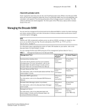
... Support Command line interface (CLI) Up to two admin sessions and four user sessions simultaneously. You can use the management functions built into the Brocade 5000 to monitor the fabric topology, port status, physical status, and other information to help you analyze switch performance and to the Brocade MIB Reference Manual. TABLE 1 Management Options for the Brocade 5000 Management Tool Out-of the management options listed in Table 1. Managing the Brocade 5000 1 FIELD REPLACEABLE UNITS Power supply/fan...
... Support Command line interface (CLI) Up to two admin sessions and four user sessions simultaneously. You can use the management functions built into the Brocade 5000 to monitor the fabric topology, port status, physical status, and other information to help you analyze switch performance and to the Brocade MIB Reference Manual. TABLE 1 Management Options for the Brocade 5000 Management Tool Out-of the management options listed in Table 1. Managing the Brocade 5000 1 FIELD REPLACEABLE UNITS Power supply/fan...

Hardware Reference
Page 15
... Guide - Rubber mounting feet (to be used when setting up the Brocade 5000 as a Standalone Unit" on page 5 - "Items Included with the standard shipment of cordset: IEC 60320/ C13 - Connector at system end of the Brocade 5000: - The power plug type is NEMA5-15 - EZSwitch Setup CD - "Setting Up the Switch Using Mounting Ears" on page 7 - "Configuring the Brocade 5000" on page 6 - The Brocade 5000 switch, containing two power supply/fan assembly units - The Brocade Documentation CD-ROM...
... Guide - Rubber mounting feet (to be used when setting up the Brocade 5000 as a Standalone Unit" on page 5 - "Items Included with the standard shipment of cordset: IEC 60320/ C13 - Connector at system end of the Brocade 5000: - The power plug type is NEMA5-15 - EZSwitch Setup CD - "Setting Up the Switch Using Mounting Ears" on page 7 - "Configuring the Brocade 5000" on page 6 - The Brocade 5000 switch, containing two power supply/fan assembly units - The Brocade Documentation CD-ROM...

Hardware Reference
Page 16
... to Power Supply Specifications on the switch. In an EIA cabinet using the mounting ears provided with the switch. For detailed installation instructions, refer to the SilkWorm Switch Safety Guide. For power supply information, refer to "Setting Up the Brocade 5000 as a Standalone Unit" on page 7. - For additional installation, electrical, environmental, and other considerations, refer to the Fixed Rack Mount Kit Installation Procedure. - Ground all times. Setting Up the Switch Using Mounting Ears The Brocade 5000 is...
... to Power Supply Specifications on the switch. In an EIA cabinet using the mounting ears provided with the switch. For detailed installation instructions, refer to the SilkWorm Switch Safety Guide. For power supply information, refer to "Setting Up the Brocade 5000 as a Standalone Unit" on page 7. - For additional installation, electrical, environmental, and other considerations, refer to the Fixed Rack Mount Kit Installation Procedure. - Ground all times. Setting Up the Switch Using Mounting Ears The Brocade 5000 is...
Hardware Reference
Page 17
... Me First document included with one hand, use three screws to fasten each one. Brocade 5000 Hardware Reference Manual 7 Publication Number: 53-1000424-03 Place the long side of the mounting ear against the side of the switch (when facing the port-side of the switch. If configuring the Brocade 5000 in the rack. 2. While supporting the switch from accidentally sliding off the supporting surface. 3. Setting Up the Brocade 5000 as...
... Me First document included with one hand, use three screws to fasten each one. Brocade 5000 Hardware Reference Manual 7 Publication Number: 53-1000424-03 Place the long side of the mounting ear against the side of the switch (when facing the port-side of the switch. If configuring the Brocade 5000 in the rack. 2. While supporting the switch from accidentally sliding off the supporting surface. 3. Setting Up the Brocade 5000 as...

Hardware Reference
Page 18
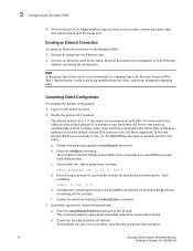
... as required • Access to avoid stress. 2. For instructions on how to the network until the IP address is supplied to the Switch Using the Serial Connection" on the left of the port side of the switch are green. Ensure that the switch power and status LEDs on page 9 4. CAUTION Power is correctly set the IP address, see "Configuring the Brocade 5000" on . 3. "Setting the Switch IP Address" on page 8 3. "Creating a Serial Connection" on page 9 5. "Completing Switch Configuration" on...
... as required • Access to avoid stress. 2. For instructions on how to the network until the IP address is supplied to the Switch Using the Serial Connection" on the left of the port side of the switch are green. Ensure that the switch power and status LEDs on page 9 4. CAUTION Power is correctly set the IP address, see "Configuring the Brocade 5000" on . 3. "Setting the Switch IP Address" on page 8 3. "Creating a Serial Connection" on page 9 5. "Completing Switch Configuration" on...

Hardware Reference
Page 19
... POST is complete, the port status and switch power and status LEDs return to display the login prompt. Committing configuration...Done. Brocade 5000 Hardware Reference Manual 9 Publication Number: 53-1000424-03 Configuring the Brocade 5000 2 1. Open a terminal emulator application (such as HyperTerminal for Windows or TERM in to "Interpreting LED Activity" on the workstation. 4. In a Windows 95, 98, 2000, or NT environment: Bits per second: 9600 Databits: 8 Parity: None Stop bits: 1 Flow control: None - Setting...
... POST is complete, the port status and switch power and status LEDs return to display the login prompt. Committing configuration...Done. Brocade 5000 Hardware Reference Manual 9 Publication Number: 53-1000424-03 Configuring the Brocade 5000 2 1. Open a terminal emulator application (such as HyperTerminal for Windows or TERM in to "Interpreting LED Activity" on the workstation. 4. In a Windows 95, 98, 2000, or NT environment: Bits per second: 9600 Databits: 8 Parity: None Stop bits: 1 Flow control: None - Setting...
Hardware Reference
Page 20
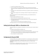
..., the switch can be accessed remotely, by command line or by typing the switchDisable command. Completing Switch Configuration To complete the switch configuration: 1. If the switch is connected to the fabric after is has been powered on until after the "Fabric parameters" prompt: Fabric parameters (yes, y, no, n): [no longer required, log out of the serial console, remove the serial cable, and replace the plug in use , the fabric segments. Disable the switch by Brocade Advanced...
..., the switch can be accessed remotely, by command line or by typing the switchDisable command. Completing Switch Configuration To complete the switch configuration: 1. If the switch is connected to the fabric after is has been powered on until after the "Fabric parameters" prompt: Fabric parameters (yes, y, no, n): [no longer required, log out of the serial console, remove the serial cable, and replace the plug in use , the fabric segments. Disable the switch by Brocade Advanced...

Hardware Reference
Page 21
... the latching mechanism clicks. Configuring the Brocade 5000 2 3. Verify the correct operation of connector) aligns with the slot in trunking groups must meet specific requirements. Position a transceiver so that the key (the ridge on page 15. 4. c. Connect the cables to "Interpreting LED Activity" on one side of the Brocade 5000 by typing the configUpload command and following the prompts. A 50-micron cable should not be bent to...
... the latching mechanism clicks. Configuring the Brocade 5000 2 3. Verify the correct operation of connector) aligns with the slot in trunking groups must meet specific requirements. Position a transceiver so that the key (the ridge on page 15. 4. c. Connect the cables to "Interpreting LED Activity" on one side of the Brocade 5000 by typing the configUpload command and following the prompts. A 50-micron cable should not be bent to...

Hardware Reference
Page 27
... cable is connected correctly. A number of Hardware Recommended Action System Status No light System is off, boot is not complete, or boot failed. Ethernet Link No light There is 10 Mb/sec. Steady amber There is 100 Mb/sec. Check the failure indicated on and power supplies are functioning properly. Port speed is a link. Steady green System is on the system console. 4. Interpreting LED Activity 3 TABLE 2 Brocade 5000 LED Patterns During Normal Operation (Continued) LED Name LED...
... cable is connected correctly. A number of Hardware Recommended Action System Status No light System is off, boot is not complete, or boot failed. Ethernet Link No light There is 10 Mb/sec. Steady amber There is 100 Mb/sec. Check the failure indicated on and power supplies are functioning properly. Port speed is a link. Steady green System is on the system console. 4. Interpreting LED Activity 3 TABLE 2 Brocade 5000 LED Patterns During Normal Operation (Continued) LED Name LED...

Hardware Reference
Page 29
... POST are run at link speeds of 1 Gbit/sec, 2 Gbit/sec, and 4 Gbit/sec. The tests are not set up for a serial connection to the switch. Some tests require loop back plugs. Brocade 5000 Hardware Reference Manual 19 Publication Number: 53-1000424-03 For information about error messages, refer to the Brocade System Message Reference. Verify that the switch prompt displays on the switch indicate that the LEDs are implemented by external cables, to allow diagnostics...
... POST are run at link speeds of 1 Gbit/sec, 2 Gbit/sec, and 4 Gbit/sec. The tests are not set up for a serial connection to the switch. Some tests require loop back plugs. Brocade 5000 Hardware Reference Manual 19 Publication Number: 53-1000424-03 For information about error messages, refer to the Brocade System Message Reference. Verify that the switch prompt displays on the switch indicate that the LEDs are implemented by external cables, to allow diagnostics...

Hardware Reference
Page 30
... fan has failed. Power supply #2 is on the cause of special tools. Type the psShow command at a time. Check the management interface and the error log for location of the following : - It will be replaced. - Check the system status LED (see Figure 3 on page 3-16 for details on the right Any of system status LED). CAUTION The Brocade 5000 has two power cords. The system software sets fan speed and measures their speeds through the tachometer interface...
... fan has failed. Power supply #2 is on the cause of special tools. Type the psShow command at a time. Check the management interface and the error log for location of the following : - It will be replaced. - Check the system status LED (see Figure 3 on page 3-16 for details on the right Any of system status LED). CAUTION The Brocade 5000 has two power cords. The system software sets fan speed and measures their speeds through the tachometer interface...
Hardware Reference
Page 38
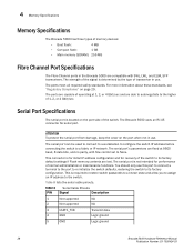
... 8 Serial Cable Pinouts PIN Signal Description 1 Not supported NA 2 Not supported NA 3 UART1_TXD Transmit data 4 GND Logic ground 5 GND Logic ground 28 Brocade 5000 Hardware Reference Manual Publication Number: 53-1000424-03 Serial Port Specifications The serial port is required to restore switch passwords to a known state and allow you to assign an IP address to its factory default settings if Flash memory contents are compatible with flow control set to a fabric or IP network. The serial port...
... 8 Serial Cable Pinouts PIN Signal Description 1 Not supported NA 2 Not supported NA 3 UART1_TXD Transmit data 4 GND Logic ground 5 GND Logic ground 28 Brocade 5000 Hardware Reference Manual Publication Number: 53-1000424-03 Serial Port Specifications The serial port is required to restore switch passwords to a known state and allow you to assign an IP address to its factory default settings if Flash memory contents are compatible with flow control set to a fabric or IP network. The serial port...

Hardware Reference
Page 39
... links. 3. Initializing hardware. 4. Enabling normal port operation. It contains: • "FCC Warning (US only)," next Brocade 5000 Hardware Reference Manual 29 Publication Number: 53-1000424-03 POST can be skipped after POST is run during POST can be monitored through LED activity, the error log, or a command-line interface. Performing universal port configuration. 2. Analyzing fabric. For more information about this command, refer to other switches, the switch participates in a minimum of three minutes if POST is complete: 1. Running diagnostic tests...
... links. 3. Initializing hardware. 4. Enabling normal port operation. It contains: • "FCC Warning (US only)," next Brocade 5000 Hardware Reference Manual 29 Publication Number: 53-1000424-03 POST can be skipped after POST is run during POST can be monitored through LED activity, the error log, or a command-line interface. Performing universal port configuration. 2. Analyzing fabric. For more information about this command, refer to other switches, the switch participates in a minimum of three minutes if POST is complete: 1. Running diagnostic tests...

Hardware Reference
Page 47
...Command line interface (CLI), 3 components, switch, 23 configuring IP address, 9 terminal emulator application, 9 D date, setting, 12 Brocade 5000 Hardware Reference Manual Publication Number: 53-1000424-03 diagnostic tests about, 19 E EIA rack requirements, 24 electrical safety, 32 environmental requirements, 26 Ethernet Port, 1 F Fabric Manager, 3 Fbre Channel classes, supported, 27 FCC warning (US only), 30 Fibre Channel Association, viii Fibre Channel ports specifications, 28 Field Replaceable Units, 3 front panel LEDs, 15 I immunity, electromagnetic, 26 installation installing the switch...
...Command line interface (CLI), 3 components, switch, 23 configuring IP address, 9 terminal emulator application, 9 D date, setting, 12 Brocade 5000 Hardware Reference Manual Publication Number: 53-1000424-03 diagnostic tests about, 19 E EIA rack requirements, 24 electrical safety, 32 environmental requirements, 26 Ethernet Port, 1 F Fabric Manager, 3 Fbre Channel classes, supported, 27 FCC warning (US only), 30 Fibre Channel Association, viii Fibre Channel ports specifications, 28 Field Replaceable Units, 3 front panel LEDs, 15 I immunity, electromagnetic, 26 installation installing the switch...

Hardware Reference
Page 48
... and humidity, 26 RJ-45 connector, 23 RS-232 connector, 23 RTC battery, 31 S Serial Port, 1 serial port specifications, 28 SNMP, 3 specifications Fibre Channel ports, 28 general, 26 power supply, 25 serial port, 28 switch components, 23 date and time, 12 installing, 5 physical dimensions, 24 weight, 24 system status LED, 15 T temperature requirements, 26 terminal emulator application, configuring, 9 tests, diagnostic, 19 time, setting, 12 trunking about, 2 cabling requirements, 11, 13 tsTimeZone, 13 U user port numbers, 2 Brocade 5000 Hardware Reference Manual Publication Number: 53-1000424-03
... and humidity, 26 RJ-45 connector, 23 RS-232 connector, 23 RTC battery, 31 S Serial Port, 1 serial port specifications, 28 SNMP, 3 specifications Fibre Channel ports, 28 general, 26 power supply, 25 serial port, 28 switch components, 23 date and time, 12 installing, 5 physical dimensions, 24 weight, 24 system status LED, 15 T temperature requirements, 26 terminal emulator application, configuring, 9 tests, diagnostic, 19 time, setting, 12 trunking about, 2 cabling requirements, 11, 13 tsTimeZone, 13 U user port numbers, 2 Brocade 5000 Hardware Reference Manual Publication Number: 53-1000424-03

