Owner's Manual
Page 46
... controls, adjust the volume, bass, or treble to eliminate distortion. If your screen. If you did not turn the player volume down or off nearby fans, fluorescent lights, or halogen lamps to the card. Sound from speakers NOTE: The volume control in some MP3 players overrides the Windows volume setting. Ensure...
... controls, adjust the volume, bass, or treble to eliminate distortion. If your screen. If you did not turn the player volume down or off nearby fans, fluorescent lights, or halogen lamps to the card. Sound from speakers NOTE: The volume control in some MP3 players overrides the Windows volume setting. Ensure...

Owner's Manual
Page 48
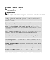
Fans, fluorescent lights, halogen lamps, and other electrical devices can cause the screen image to read C H E C K T H E M O N I T O R S E T T I N G S - M O V E T H E S U B W O O F E R A W A Y F R O M T H E M O N I T O R A W A Y F R O M E X T E R N A L P O W E R S O U R C E S - M O V E T H E M O N I T O R - ROTATE THE MONITOR TO ELIMINATE SUNLIGHT GLARE AND POSSIBLE INTERFERENCE ...
Fans, fluorescent lights, halogen lamps, and other electrical devices can cause the screen image to read C H E C K T H E M O N I T O R S E T T I N G S - M O V E T H E S U B W O O F E R A W A Y F R O M T H E M O N I T O R A W A Y F R O M E X T E R N A L P O W E R S O U R C E S - M O V E T H E M O N I T O R - ROTATE THE MONITOR TO ELIMINATE SUNLIGHT GLARE AND POSSIBLE INTERFERENCE ...
Owner's Manual
Page 65
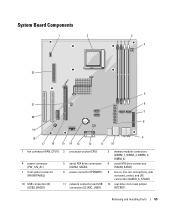
System Board Components 1 2 3 4 22 5 21 6 7 20 8 19 18 9 17 16 15 14 13 12 11 10 1 fan connector (FAN_CPU1) 2 processor socket (CPU) 4 power connector (PW_12V_A1) 7 front-panel connector (FRONTPANEL) 10 USB connectors (2) (USB2_BACK1) 5 serial ATA drive connectors (SATA2, SATA3) 8 power connector (POWER1) ...
System Board Components 1 2 3 4 22 5 21 6 7 20 8 19 18 9 17 16 15 14 13 12 11 10 1 fan connector (FAN_CPU1) 2 processor socket (CPU) 4 power connector (PW_12V_A1) 7 front-panel connector (FRONTPANEL) 10 USB connectors (2) (USB2_BACK1) 5 serial ATA drive connectors (SATA2, SATA3) 8 power connector (POWER1) ...

Owner's Manual
Page 95
.... 12 Verify that your computer and devices to avoid blocking airflow between the fan and cooling vents. 8 Replace the drive panel (see "Replacing the Drive Panel" on page 84). 9 Replace the computer cover (see "Dell Diagnostics" on page 105). NOTICE: To connect a network cable, first plug... the cable into the network device and then plug it into the computer. 10 Connect your computer works correctly by running the Dell Diagnostics (see "Replacing the Computer Cover" on...
.... 12 Verify that your computer and devices to avoid blocking airflow between the fan and cooling vents. 8 Replace the drive panel (see "Replacing the Drive Panel" on page 84). 9 Replace the computer cover (see "Dell Diagnostics" on page 105). NOTICE: To connect a network cable, first plug... the cable into the network device and then plug it into the computer. 10 Connect your computer works correctly by running the Dell Diagnostics (see "Replacing the Computer Cover" on...

Owner's Manual
Page 103
... 10 Verify that your computer and devices to avoid blocking airflow between the fan and cooling vents. 6 Replace the drive panel (see "Replacing the Drive Panel" on page 84). 7 Replace the computer cover (see "Dell Diagnostics" on . Removing and Installing Parts 103 NOTICE: To connect a network... cable, first plug the cable into the network device and then plug it into the computer. 8 Connect your computer works correctly by running the Dell Diagnostics (see "Replacing the Computer Cover" on page 105). 1 2 1 power cable 2 data cable 5 Check all cable connections, and fold ...
... 10 Verify that your computer and devices to avoid blocking airflow between the fan and cooling vents. 6 Replace the drive panel (see "Replacing the Drive Panel" on page 84). 7 Replace the computer cover (see "Dell Diagnostics" on . Removing and Installing Parts 103 NOTICE: To connect a network... cable, first plug the cable into the network device and then plug it into the computer. 8 Connect your computer works correctly by running the Dell Diagnostics (see "Replacing the Computer Cover" on page 105). 1 2 1 power cable 2 data cable 5 Check all cable connections, and fold ...
Owner's Manual
Page 109
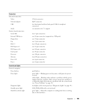
... Problems" on the system board green light - Connectors External connectors: Video Network adapter USB Audio System board connectors: Serial ATA Internal USB device Floppy drive Fan PCI 2.3 PCI Express x1 PCI Express x16 Front panel Processor Memory Power 12V Power Controls and Lights Front of computer: Power button Power light Diagnostic...
... Problems" on the system board green light - Connectors External connectors: Video Network adapter USB Audio System board connectors: Serial ATA Internal USB device Floppy drive Fan PCI 2.3 PCI Express x1 PCI Express x16 Front panel Processor Memory Power 12V Power Controls and Lights Front of computer: Power button Power light Diagnostic...


