
Owner's Manual
Page 10
...detects your computer and operating system and installs the updates appropriate for Dell™ 3.5-inch USB floppy drives, Intel® Pentium® M processors, optical drives, and USB devices. support.dell.com from technicians, and online courses, frequently asked NOTE: Select your... 4 Select the operating system and operating system language for correct operation of your Dell computer. Upgrade information for your computer, you use the customized Dell Premier Support website at • Upgrades - Computer documentation, details on your computer. • Use the Service Tag ...
...detects your computer and operating system and installs the updates appropriate for Dell™ 3.5-inch USB floppy drives, Intel® Pentium® M processors, optical drives, and USB devices. support.dell.com from technicians, and online courses, frequently asked NOTE: Select your... 4 Select the operating system and operating system language for correct operation of your Dell computer. Upgrade information for your computer, you use the customized Dell Premier Support website at • Upgrades - Computer documentation, details on your computer. • Use the Service Tag ...

Owner's Manual
Page 69
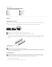
... safety instructions located in the Product Information Guide. NOTICE: To prevent static damage to processor securing clips (2) connector 3 Align the notch on the bottom of the memory module ...connector. NOTICE: If you remove your original memory modules from the computer during a memory upgrade, keep them separate from any new modules that you may not start properly. memory connector... closest to components inside your computer, discharge static electricity from Dell. If possible, do so by touching an unpainted metal surface on page 57. ...
... safety instructions located in the Product Information Guide. NOTICE: To prevent static damage to processor securing clips (2) connector 3 Align the notch on the bottom of the memory module ...connector. NOTICE: If you remove your original memory modules from the computer during a memory upgrade, keep them separate from any new modules that you may not start properly. memory connector... closest to components inside your computer, discharge static electricity from Dell. If possible, do so by touching an unpainted metal surface on page 57. ...
Service Manual
Page 14
...memory module connector. For additional information on the type of your original memory modules from the computer during a memory upgrade, keep them separate from Dell is supported. NOTICE: Do not install ECC or buffered memory modules. NOTICE: If you remove your computer's ...your computer, discharge static electricity from Dell. Back to Contents Page Removing and Installing Parts Dell™ Dimension™ 3100/E310 Service Manual Memory Cards Drive Panels Drives Hard Drive Floppy Drive Media Card Reader CD/DVD Drive Processor System Board Power Supply Battery Memory...
...memory module connector. For additional information on the type of your original memory modules from the computer during a memory upgrade, keep them separate from Dell is supported. NOTICE: Do not install ECC or buffered memory modules. NOTICE: If you remove your computer's ...your computer, discharge static electricity from Dell. Back to Contents Page Removing and Installing Parts Dell™ Dimension™ 3100/E310 Service Manual Memory Cards Drive Panels Drives Hard Drive Floppy Drive Media Card Reader CD/DVD Drive Processor System Board Power Supply Battery Memory...

Service Manual
Page 34
... computer. 1 heat sink and fan shroud assembly 2 captive screw housings (2) NOTICE: If you install your new processor. 4. If you are installing a processor upgrade kit from Dell, reuse the original heat sink when you are not installing a processor upgrade kit from Dell, discard the original heat sink. Leave the release lever extended in the socket. 5. 3. Gently remove the...
... computer. 1 heat sink and fan shroud assembly 2 captive screw housings (2) NOTICE: If you install your new processor. 4. If you are installing a processor upgrade kit from Dell, reuse the original heat sink when you are not installing a processor upgrade kit from Dell, discard the original heat sink. Leave the release lever extended in the socket. 5. 3. Gently remove the...

Service Manual
Page 35
... the socket is positioned correctly. 6. NOTICE: If you are not installing a processor upgrade kit from Dell, return the original heat sink assembly and processor to touch the underside of the processor and socket. 1 processor cover 6 release lever 2 tab 7 front alignment notch 3 processor 8 socket and processor pin-1 indicator 4 processor socket 9 rear alignment notch 5 center cover latch NOTICE: To avoid damage...
... the socket is positioned correctly. 6. NOTICE: If you are not installing a processor upgrade kit from Dell, return the original heat sink assembly and processor to touch the underside of the processor and socket. 1 processor cover 6 release lever 2 tab 7 front alignment notch 3 processor 8 socket and processor pin-1 indicator 4 processor socket 9 rear alignment notch 5 center cover latch NOTICE: To avoid damage...


