Owner's Manual
Page 5
...50 If the screen is blank 50 If the screen is difficult to read 51 3 Troubleshooting Tools 53 Diagnostic Lights 53 Dell Diagnostics 56 Dell Diagnostics Main Menu 56 Drivers 57 What Is a Driver 57 Identifying Drivers 58 Reinstalling Drivers 58 Resolving Software and Hardware ...Incompatibilities 59 Restoring Your Operating System 59 Using Microsoft Windows XP System Restore 60 Using Dell PC Restore by Symantec 61 4 Removing and Installing Parts 63 Before You Begin 63 Recommended Tools 63 Turn Off Your Computer 63 Before Working Inside Your Computer...
...50 If the screen is blank 50 If the screen is difficult to read 51 3 Troubleshooting Tools 53 Diagnostic Lights 53 Dell Diagnostics 56 Dell Diagnostics Main Menu 56 Drivers 57 What Is a Driver 57 Identifying Drivers 58 Reinstalling Drivers 58 Resolving Software and Hardware ...Incompatibilities 59 Restoring Your Operating System 59 Using Microsoft Windows XP System Restore 60 Using Dell PC Restore by Symantec 61 4 Removing and Installing Parts 63 Before You Begin 63 Recommended Tools 63 Turn Off Your Computer 63 Before Working Inside Your Computer...
Owner's Manual
Page 28
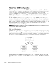
Although several RAID configurations are available, Dell offers either a RAID level 0 configuration or a RAID level 1 configuration ...the larger drive does not contain unallocated (and therefore unusable) space. A RAID level 0 configuration is recommended for its Dimension™ computers. NOTE: RAID levels do not represent a hierarchy. RAID Level 0 Configuration A RAID level 0 configuration ...can be used as "data striping" to ensure that you purchased your computer can be made part of the drives. For example, if you have two 120-GB drives installed, you have selected...
Although several RAID configurations are available, Dell offers either a RAID level 0 configuration or a RAID level 1 configuration ...the larger drive does not contain unallocated (and therefore unusable) space. A RAID level 0 configuration is recommended for its Dimension™ computers. NOTE: RAID levels do not represent a hierarchy. RAID Level 0 Configuration A RAID level 0 configuration ...can be used as "data striping" to ensure that you purchased your computer can be made part of the drives. For example, if you have two 120-GB drives installed, you have selected...

Owner's Manual
Page 37
...section, follow the safety instructions in a program, see the program's documentation. • If you added or removed a part before the problem started, review the installation procedures and ensure that the device is properly connected. • If an error ... page 126). CAUTION: Before you begin any of a new battery exploding if it is correctly installed. • If a peripheral device does not work properly, contact Dell (see page 106). Discard used batteries according to repeatedly reset time and date information after turning on the screen, write down the exact message. R E P L...
...section, follow the safety instructions in a program, see the program's documentation. • If you added or removed a part before the problem started, review the installation procedures and ensure that the device is properly connected. • If an error ... page 126). CAUTION: Before you begin any of a new battery exploding if it is correctly installed. • If a peripheral device does not work properly, contact Dell (see page 106). Discard used batteries according to repeatedly reset time and date information after turning on the screen, write down the exact message. R E P L...
Owner's Manual
Page 56
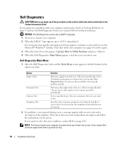
...Lists the most common symptoms encountered and allows you to select a test based on page 37 and run the Dell Diagnostics before you to 20 minutes and requires no interaction on your part. NOTE: The Service Tag for your computer is encountered during a test, a message appears with your computer... (see page 63) and try again. 3 When the boot device list appears, highlight Boot to Utility Partition and press . 4 When the Dell Diagnostics Main Menu appears,...
...Lists the most common symptoms encountered and allows you to select a test based on page 37 and run the Dell Diagnostics before you to 20 minutes and requires no interaction on your part. NOTE: The Service Tag for your computer is encountered during a test, a message appears with your computer... (see page 63) and try again. 3 When the boot device list appears, highlight Boot to Utility Partition and press . 4 When the Dell Diagnostics Main Menu appears,...
Owner's Manual
Page 63
... the safety information in your operating system, press and hold the power button for removing and installing the components in your computer. 1 Shut down your Dell™ Product Information Guide. • A component can be replaced by performing the removal procedure in this document may require the following tools: • Small flat...: To avoid losing data, save and close any open files, exit any open files and exit any attached devices are turned off . Removing and Installing Parts 63 Recommended Tools The procedures in reverse order. Removing and Installing...
... the safety information in your operating system, press and hold the power button for removing and installing the components in your computer. 1 Shut down your Dell™ Product Information Guide. • A component can be replaced by performing the removal procedure in this document may require the following tools: • Small flat...: To avoid losing data, save and close any open files, exit any open files and exit any attached devices are turned off . Removing and Installing Parts 63 Recommended Tools The procedures in reverse order. Removing and Installing...
Owner's Manual
Page 64
...: When you work, periodically touch an unpainted metal surface to dissipate any static electricity that could harm internal components. 64 Removing and Installing Parts Also, before you disconnect the cable. NOTICE: Before touching anything inside the computer. 1 Turn off your computer. if you are disconnecting ...connector or on its strain-relief loop, not on the locking tabs before you connect a cable, ensure that is not authorized by Dell is not covered by its metal mounting bracket. As you begin working inside your computer, ground yourself by touching an unpainted metal ...
...: When you work, periodically touch an unpainted metal surface to dissipate any static electricity that could harm internal components. 64 Removing and Installing Parts Also, before you disconnect the cable. NOTICE: Before touching anything inside the computer. 1 Turn off your computer. if you are disconnecting ...connector or on its strain-relief loop, not on the locking tabs before you connect a cable, ensure that is not authorized by Dell is not covered by its metal mounting bracket. As you begin working inside your computer, ground yourself by touching an unpainted metal ...
Owner's Manual
Page 65
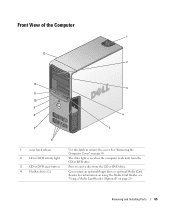
The drive light is on page 20. For information on using the Media Card Reader, see "Using a Media Card Reader (Optional)" on when the computer reads data from the CD or DVD drive. Can contain an optional floppy drive or optional Media Card Reader. See "Removing the Computer Cover" on page 68. Front View of the Computer 1 13 2 12 3 11 10 9 8 4 7 5 6 1 cover latch release 2 CD or DVD activity light 3 CD or DVD eject button 4 FlexBay drives (2) Use this latch to eject a disc from the CD or DVD drive. Press to remove the cover. Removing and Installing Parts 65
The drive light is on page 20. For information on using the Media Card Reader, see "Using a Media Card Reader (Optional)" on when the computer reads data from the CD or DVD drive. Can contain an optional floppy drive or optional Media Card Reader. See "Removing the Computer Cover" on page 68. Front View of the Computer 1 13 2 12 3 11 10 9 8 4 7 5 6 1 cover latch release 2 CD or DVD activity light 3 CD or DVD eject button 4 FlexBay drives (2) Use this latch to eject a disc from the CD or DVD drive. Press to remove the cover. Removing and Installing Parts 65

Owner's Manual
Page 66
... button to a USB device). For adequate cooling, do not use the back USB connectors for devices that you access the Dell Support website or call technical support. 66 Removing and Installing Parts Instead, perform an operating system shutdown. For more information on booting to turn on page 53. 5 IEEE 1394 connector (optional...
... button to a USB device). For adequate cooling, do not use the back USB connectors for devices that you access the Dell Support website or call technical support. 66 Removing and Installing Parts Instead, perform an operating system shutdown. For more information on booting to turn on page 53. 5 IEEE 1394 connector (optional...

Owner's Manual
Page 67
Removing and Installing Parts 67 Use the green line-out connector to attach multiple speakers. Use the yellow subwoofer connector to attach headphones and most speakers with integrated amplifiers. &#...
Removing and Installing Parts 67 Use the green line-out connector to attach multiple speakers. Use the yellow subwoofer connector to attach headphones and most speakers with integrated amplifiers. &#...

Owner's Manual
Page 68
... harm internal components. 1 Follow the procedures in the Product Information Guide. It is resting. 3 Lay your computer on the top panel. 68 Removing and Installing Parts NOTICE: Ensure that you use Category 3 wiring, force the network speed to 10 Mbps to ensure reliable operation. Use the back USB connectors for any...
... harm internal components. 1 Follow the procedures in the Product Information Guide. It is resting. 3 Lay your computer on the top panel. 68 Removing and Installing Parts NOTICE: Ensure that you use Category 3 wiring, force the network speed to 10 Mbps to ensure reliable operation. Use the back USB connectors for any...

Owner's Manual
Page 69
cover latch release computer cover back of computer hinge tabs (3) 5 Locate the three hinge tabs on the bottom edge of the computer. 6 Grip the sides of the computer cover and pivot the cover up. 7 Lift the cover away and set it aside in a secure location. Removing and Installing Parts 69
cover latch release computer cover back of computer hinge tabs (3) 5 Locate the three hinge tabs on the bottom edge of the computer. 6 Grip the sides of the computer cover and pivot the cover up. 7 Lift the cover away and set it aside in a secure location. Removing and Installing Parts 69

Owner's Manual
Page 70
power supply system board CD or DVD drive *floppy drive *may not be present on all computers hard drive 70 Removing and Installing Parts Inside View of Your Computer CAUTION: Before you begin any of the procedures in this section, follow the safety instructions in the Product Information Guide.
power supply system board CD or DVD drive *floppy drive *may not be present on all computers hard drive 70 Removing and Installing Parts Inside View of Your Computer CAUTION: Before you begin any of the procedures in this section, follow the safety instructions in the Product Information Guide.
Owner's Manual
Page 71
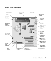
... (RTCRST) FlexBay USB connector PCI Express x1 card connector PCI Express x16 card connector PCI Express x4 card connector PCI card connectors Removing and Installing Parts 71
... (RTCRST) FlexBay USB connector PCI Express x1 card connector PCI Express x16 card connector PCI Express x4 card connector PCI card connectors Removing and Installing Parts 71

Owner's Manual
Page 72
... to install a single memory module in connectors DIMM_3 and DIMM_4 • If you do not mix ECC and non-ECC memory. 72 Removing and Installing Parts A pair of matched memory modules installed in the order indicated on the type of matched memory modules installed in connectors DIMM_1 and DIMM_2 and another...
... to install a single memory module in connectors DIMM_3 and DIMM_4 • If you do not mix ECC and non-ECC memory. 72 Removing and Installing Parts A pair of matched memory modules installed in the order indicated on the type of matched memory modules installed in connectors DIMM_1 and DIMM_2 and another...
Owner's Manual
Page 73
Addressing Memory With 4-GB Configurations Your computer supports a maximum of 4 GB of memory when you purchased the new modules from Dell. Removing and Installing Parts 73 Otherwise, your original memory modules in pairs either in connectors DIMM_1 and DIMM_2 or connectors DIMM_3 and DIMM_4. If possible, do not pair an ... connectors DIMM_1 and DIMM_2 (white securing clips) Channel B: matched pair of memory modules in connectors DIMM_3 and DIMM_4 (black securing clips) NOTE: Memory purchased from Dell is less than 4 GB. NOTICE: If you remove your computer warranty.
Addressing Memory With 4-GB Configurations Your computer supports a maximum of 4 GB of memory when you purchased the new modules from Dell. Removing and Installing Parts 73 Otherwise, your original memory modules in pairs either in connectors DIMM_1 and DIMM_2 or connectors DIMM_3 and DIMM_4. If possible, do not pair an ... connectors DIMM_1 and DIMM_2 (white securing clips) Channel B: matched pair of memory modules in connectors DIMM_3 and DIMM_4 (black securing clips) NOTE: Memory purchased from Dell is less than 4 GB. NOTICE: If you remove your computer warranty.

Owner's Manual
Page 74
... on the computer. 1 Follow the procedures in the Product Information Guide. NOTICE: To prevent static damage to processor securing clips (2) connector 74 Removing and Installing Parts memory connector closest to components inside of the computer. 4 Press out the securing clip at each end of your computer's electronic components. You can do...
... on the computer. 1 Follow the procedures in the Product Information Guide. NOTICE: To prevent static damage to processor securing clips (2) connector 74 Removing and Installing Parts memory connector closest to components inside of the computer. 4 Press out the securing clip at each end of your computer's electronic components. You can do...

Owner's Manual
Page 75
Removing and Installing Parts 75 If you apply equal force to the memory module, press the module straight down into the connector while you insert the module correctly, the ...
Removing and Installing Parts 75 If you apply equal force to the memory module, press the module straight down into the connector while you insert the module correctly, the ...
Owner's Manual
Page 76
... into the computer. 8 Connect your computer's electronic components. If the module is installed correctly, check the amount of memory (RAM) listed. Your Dell™ computer provides the following slots for PCI and PCI Express cards: • Three PCI card slots • One PCI Express x1 card slot... • One PCI Express x16 card slot • One PCI Express x4 card slot 76 Removing and Installing Parts NOTICE: To prevent static damage to components inside your computer, discharge static electricity from your body before you touch any of your computer and...
... into the computer. 8 Connect your computer's electronic components. If the module is installed correctly, check the amount of memory (RAM) listed. Your Dell™ computer provides the following slots for PCI and PCI Express cards: • Three PCI card slots • One PCI Express x1 card slot... • One PCI Express x16 card slot • One PCI Express x4 card slot 76 Removing and Installing Parts NOTICE: To prevent static damage to components inside your computer, discharge static electricity from your body before you touch any of your computer and...

Owner's Manual
Page 77
... and IEEE 1394 PCI add-in-cards that includes a front-mounted IEEE 1394 connector. 1 Follow the procedures in the next section. Installing a PCI Card NOTE: Dell offers an optional customer kit for the card from the operating system. If you are installing or replacing a PCI Express card, see "Installing a PCI Express... Card" on page 80". release tabs (2) card retention door alignment bar alignment guide filler bracket Removing and Installing Parts 77 If you are removing but not replacing a card, see page 68).
... and IEEE 1394 PCI add-in-cards that includes a front-mounted IEEE 1394 connector. 1 Follow the procedures in the next section. Installing a PCI Card NOTE: Dell offers an optional customer kit for the card from the operating system. If you are installing or replacing a PCI Express card, see "Installing a PCI Express... Card" on page 80". release tabs (2) card retention door alignment bar alignment guide filler bracket Removing and Installing Parts 77 If you are removing but not replacing a card, see page 68).

Owner's Manual
Page 78
... to release the mechanism from the inside to the card. release tab card retention mechanism card retention door 4 If your computer. 78 Removing and Installing Parts Then continue with the card for information on the card retention door from the two tab slots holding it in place. 3 Push the two release...
... to release the mechanism from the inside to the card. release tab card retention mechanism card retention door 4 If your computer. 78 Removing and Installing Parts Then continue with the card for information on the card retention door from the two tab slots holding it in place. 3 Push the two release...


