Dell Dimension 2100 Solutions Guide
Page 5
... Last System Restore 52 Reinstalling Windows XP 53 Reinstalling Windows Me 55 Reinstalling Windows 2000 57 3 Adding Parts Removing the Computer Cover 60 Rotating the Power Supply 62 Looking Inside Your Computer 65 System Board 66 Adding a 3.5-Inch Drive 67 Adding Cards 73 Removing Cards 77 Adding Memory 78 Replacing the Computer...
... Last System Restore 52 Reinstalling Windows XP 53 Reinstalling Windows Me 55 Reinstalling Windows 2000 57 3 Adding Parts Removing the Computer Cover 60 Rotating the Power Supply 62 Looking Inside Your Computer 65 System Board 66 Adding a 3.5-Inch Drive 67 Adding Cards 73 Removing Cards 77 Adding Memory 78 Replacing the Computer...

Dell Dimension 2100 Solutions Guide
Page 8
... remove the grounding prong from radiators and heat sources. If the computer gets wet, contact Dell (see page 92). • Do not push any objects into properly grounded power sources. Special shelves are not located where they can cause fire or electric shock by shorting...; Keep your computer away from a cable. Ergonomic Computing Habits CAUTION: Improper or prolonged keyboard use a surge suppressor, line conditioner, or uninterruptible power supply. • Be sure that nothing rests on your keyboard. • Set the monitor at eye level or slightly lower when you are directly...
... remove the grounding prong from radiators and heat sources. If the computer gets wet, contact Dell (see page 92). • Do not push any objects into properly grounded power sources. Special shelves are not located where they can cause fire or electric shock by shorting...; Keep your computer away from a cable. Ergonomic Computing Habits CAUTION: Improper or prolonged keyboard use a surge suppressor, line conditioner, or uninterruptible power supply. • Be sure that nothing rests on your keyboard. • Set the monitor at eye level or slightly lower when you are directly...

Dell Dimension 2100 Solutions Guide
Page 59
SECTION 3 Removing the Computer Cover Rotating the Power Supply Looking Inside Your Computer Adding a 3.5-Inch Drive Adding Cards Adding Memory Replacing the Computer Cover www.dell.com | support.dell.com
SECTION 3 Removing the Computer Cover Rotating the Power Supply Looking Inside Your Computer Adding a 3.5-Inch Drive Adding Cards Adding Memory Replacing the Computer Cover www.dell.com | support.dell.com

Dell Dimension 2100 Solutions Guide
Page 62
Pressing the power button when the computer is not connected to the computer, you begin any of the way: 1 Turn off the computer and devices, and disconnect them ... to an electrical outlet discharges residual electricity and can help prevent system board damage. 3 Remove the computer cover (see page 60). 62 Adding Parts www.dell.com | support.dell.com CAUTION: Before you must rotate the power supply out of the procedures in this section, follow the safety instructions on the wall. 2 Press the...
Pressing the power button when the computer is not connected to the computer, you begin any of the way: 1 Turn off the computer and devices, and disconnect them ... to an electrical outlet discharges residual electricity and can help prevent system board damage. 3 Remove the computer cover (see page 60). 62 Adding Parts www.dell.com | support.dell.com CAUTION: Before you must rotate the power supply out of the procedures in this section, follow the safety instructions on the wall. 2 Press the...

Dell Dimension 2100 Solutions Guide
Page 63
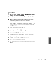
Rotate the power supply out of the computer while keeping the drive power cables clear. power supply release latch drive power cables Adding Parts 63 4 Lay the computer on its side as shown in the following illustration. Press the release latch while lifting the power supply.
Rotate the power supply out of the computer while keeping the drive power cables clear. power supply release latch drive power cables Adding Parts 63 4 Lay the computer on its side as shown in the following illustration. Press the release latch while lifting the power supply.

Dell Dimension 2100 Solutions Guide
Page 64
Lay the drive power cables along the top of the way. Rotate the power supply into the computer, gently lift the and hold the drive cables out of the latch. power supply drive power cables 64 Adding Parts www.dell.com | support.dell.com When you rotate the power supply back into position until its release latch clicks.
Lay the drive power cables along the top of the way. Rotate the power supply into the computer, gently lift the and hold the drive cables out of the latch. power supply drive power cables 64 Adding Parts www.dell.com | support.dell.com When you rotate the power supply back into position until its release latch clicks.

Dell Dimension 2100 Solutions Guide
Page 65
release latch and padlock ring I/O panel drive bay drive bay hard drive power supply AC power receptacle Adding Parts 65 CAUTION: Before you begin any of the procedures in this section, follow the safety instructions on page 7.
release latch and padlock ring I/O panel drive bay drive bay hard drive power supply AC power receptacle Adding Parts 65 CAUTION: Before you begin any of the procedures in this section, follow the safety instructions on page 7.

Dell Dimension 2100 Solutions Guide
Page 70
Using a screwdriver, pop out the metal plate from the left or right side of the computer. drive bay plate 70 Adding Parts www.dell.com | support.dell.com 6 Rotate the power supply (see page 62). 7 Remove the metal drive bay plate covering the bay.
Using a screwdriver, pop out the metal plate from the left or right side of the computer. drive bay plate 70 Adding Parts www.dell.com | support.dell.com 6 Rotate the power supply (see page 62). 7 Remove the metal drive bay plate covering the bay.

Dell Dimension 2100 Solutions Guide
Page 72
... the wide cable connector and reattach the connector to the system board. If you didn't install a controller card in step 10, remove the tape from power supply NOTICE: When you attach the extra connector to the new drive in the following step, match the colored strip on the cable with pin 1 on... original drive. Be sure that the wide cable is properly connected to the IDE connector on the cable and attach it to the drive. www.dell.com | support.dell.com 11 Connect a power cable to the new drive.
... the wide cable connector and reattach the connector to the system board. If you didn't install a controller card in step 10, remove the tape from power supply NOTICE: When you attach the extra connector to the new drive in the following step, match the colored strip on the cable with pin 1 on... original drive. Be sure that the wide cable is properly connected to the IDE connector on the cable and attach it to the drive. www.dell.com | support.dell.com 11 Connect a power cable to the new drive.
Dell Dimension 2100 Solutions Guide
Page 73
... the computer until the front panel latches into position. 14 Make sure that they will not interfere with replacing the power supply and computer cover. 15 Rotate the power supply back into place (see page 64). 16 Replace the computer cover (see page 80). 17 Plug your computer and...an electrical outlet discharges residual electricity and can help prevent system board damage. 3 Remove the computer cover (see page 60). 4 Rotate the power supply (see page 68). Arrange cables so that no cable connections were loosened during the procedure. CAUTION: Before you begin any software required for ...
... the computer until the front panel latches into position. 14 Make sure that they will not interfere with replacing the power supply and computer cover. 15 Rotate the power supply back into place (see page 64). 16 Replace the computer cover (see page 80). 17 Plug your computer and...an electrical outlet discharges residual electricity and can help prevent system board damage. 3 Remove the computer cover (see page 60). 4 Rotate the power supply (see page 68). Arrange cables so that no cable connections were loosened during the procedure. CAUTION: Before you begin any software required for ...

Dell Dimension 2100 Solutions Guide
Page 76
fully seated not fully seated bracket within the card slot. www.dell.com | support.dell.com Make sure that the card is fully seated and that its bracket is within slot bracket caught outside of slot 7 Secure the bracket on ... of the card with the screw you removed in step 5. 8 Connect any cables required for the card as described in the card documentation. 9 Rotate the power supply back into place (see page 64). 10 Replace the computer cover (see page 80). 11 Plug your computer and devices into their electrical outlets, and...
fully seated not fully seated bracket within the card slot. www.dell.com | support.dell.com Make sure that the card is fully seated and that its bracket is within slot bracket caught outside of slot 7 Secure the bracket on ... of the card with the screw you removed in step 5. 8 Connect any cables required for the card as described in the card documentation. 9 Rotate the power supply back into place (see page 64). 10 Replace the computer cover (see page 80). 11 Plug your computer and devices into their electrical outlets, and...
Dell Dimension 2100 Solutions Guide
Page 77
...electrical outlet discharges residual electricity and can help prevent system board damage. 3 Remove the computer cover (see page 60). 4 Rotate the power supply (see page 80). 11 Plug your computer and then unplug it from their electrical outlets, and turn them from the system board. ...8 If you are removing the card permanently, reinstall a filler bracket. 9 Rotate the power supply back into their electrical outlets. Removing Cards CAUTION: Before you begin any cables connected to the card. 6 Remove the screw from the card ...
...electrical outlet discharges residual electricity and can help prevent system board damage. 3 Remove the computer cover (see page 60). 4 Rotate the power supply (see page 80). 11 Plug your computer and then unplug it from their electrical outlets, and turn them from the system board. ...8 If you are removing the card permanently, reinstall a filler bracket. 9 Rotate the power supply back into their electrical outlets. Removing Cards CAUTION: Before you begin any cables connected to the card. 6 Remove the screw from the card ...

Dell Dimension 2100 Solutions Guide
Page 78
...installing memory modules on the system board. You can help prevent system board damage. 3 Open the computer cover (see page 60). 4 Rotate the power supply (see page 62). 5 If necessary, remove a memory module: a Press out the securing clip at each end of the procedures in this section,... wall. 2 Press the power button. If the module is difficult to remove, gently ease the module back and forth to an electrical outlet discharges residual electricity and can increase your computer warranty. www.dell.com | support.dell.com HINT: Memory purchased from Dell is covered under your computer...
...installing memory modules on the system board. You can help prevent system board damage. 3 Open the computer cover (see page 60). 4 Rotate the power supply (see page 62). 5 If necessary, remove a memory module: a Press out the securing clip at each end of the procedures in this section,... wall. 2 Press the power button. If the module is difficult to remove, gently ease the module back and forth to an electrical outlet discharges residual electricity and can increase your computer warranty. www.dell.com | support.dell.com HINT: Memory purchased from Dell is covered under your computer...

Dell Dimension 2100 Solutions Guide
Page 80
... screws) are left sides of the way so that might have come loose during your work. Replace the computer cover: 1 Rotate the power supply back into place (see the following section). Fold cables and unused connectors out of the computer together until the cover clicks into position. 80... Adding Parts www.dell.com | support.dell.com HINT: The system memory value reported by the operating system is 1 or 2 MB less than the memory installed because that memory is reserved for video functions. 9 Rotate the power supply back into place (see page 64). 10 ...
... screws) are left sides of the way so that might have come loose during your work. Replace the computer cover: 1 Rotate the power supply back into place (see the following section). Fold cables and unused connectors out of the computer together until the cover clicks into position. 80... Adding Parts www.dell.com | support.dell.com HINT: The system memory value reported by the operating system is 1 or 2 MB less than the memory installed because that memory is reserved for video functions. 9 Rotate the power supply back into place (see page 64). 10 ...
Dell Dimension 2100 Solutions Guide
Page 84
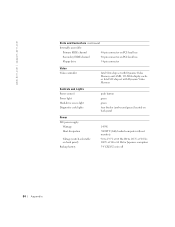
www.dell.com | support.dell.com Ports and Connectors (continued) Internally accessible: Primary EIDE channel 40-pin connector on PCI local bus Secondary EIDE channel 40-pin connector on PCI ... Hard-drive access light Diagnostic code lights push button green green four bicolor (amber and green) located on back panel Power DC power supply: Wattage Heat dissipation Voltage (switch-selectable on back panel) Backup battery 145 W 700 BTU (fully loaded computer without monitor) 90 to 135 V at 60 Hz;...
www.dell.com | support.dell.com Ports and Connectors (continued) Internally accessible: Primary EIDE channel 40-pin connector on PCI local bus Secondary EIDE channel 40-pin connector on PCI ... Hard-drive access light Diagnostic code lights push button green green four bicolor (amber and green) located on back panel Power DC power supply: Wattage Heat dissipation Voltage (switch-selectable on back panel) Backup battery 145 W 700 BTU (fully loaded computer without monitor) 90 to 135 V at 60 Hz;...

Dell Dimension 2100 Solutions Guide
Page 87
.... Main provides settings for the hardware installed in your computer or change settings in brackets, but not those that pins 2 and 3 are jumpered. 4 Rotate the power supply back into the following procedure resets all current settings so that you can change settings enclosed in the system setup program until you finish this...
.... Main provides settings for the hardware installed in your computer or change settings in brackets, but not those that pins 2 and 3 are jumpered. 4 Rotate the power supply back into the following procedure resets all current settings so that you can change settings enclosed in the system setup program until you finish this...

Dell Dimension 2100 Solutions Guide
Page 88
...pins 1 and 2 are jumpered (standard setting). 11 Rotate the power supply back into place (see page 60). 88 Appendix Replace the 3-V CR2032 battery only with the same or equivalent type recommended by the manufacturer. www.dell.com | support.dell.com 5 Replace the computer cover (see page 80), plug your... changes and exit the system setup program. 8 Remove the computer cover again. 9 Rotate the power supply (see page 62). 10 Move the jumper plug so...
...pins 1 and 2 are jumpered (standard setting). 11 Rotate the power supply back into place (see page 60). 88 Appendix Replace the 3-V CR2032 battery only with the same or equivalent type recommended by the manufacturer. www.dell.com | support.dell.com 5 Replace the computer cover (see page 80), plug your... changes and exit the system setup program. 8 Remove the computer cover again. 9 Rotate the power supply (see page 62). 10 Move the jumper plug so...

Dell Dimension 2100 Solutions Guide
Page 89
... fingers or with the side labeled "+" facing up. Appendix 89 NOTICE: To avoid damage to the system board while you recorded in step 1. 3 Rotate the power supply (see page 66) and pry the battery out of its socket with your computer and devices into the socket with a plastic screwdriver. 5 Insert the battery...
... fingers or with the side labeled "+" facing up. Appendix 89 NOTICE: To avoid damage to the system board while you recorded in step 1. 3 Rotate the power supply (see page 66) and pry the battery out of its socket with your computer and devices into the socket with a plastic screwdriver. 5 Insert the battery...

Dell Dimension 2100 Solutions Guide
Page 136
... fixing problems, 34 N network fixing problems, 39 setting up, 18 Network Setup Wizard, 18 P password clearing system setup, 87 PCI card, 73 power fixing problems, 25 turning off, 18 power supply rotating, 62 printer connecting, 14 fixing problems, 29 reinstalling driver, 16 setting up , 25 Windows, 39 modem fixing problems, 32 monitor fixing...
... fixing problems, 34 N network fixing problems, 39 setting up, 18 Network Setup Wizard, 18 P password clearing system setup, 87 PCI card, 73 power fixing problems, 25 turning off, 18 power supply rotating, 62 printer connecting, 14 fixing problems, 29 reinstalling driver, 16 setting up , 25 Windows, 39 modem fixing problems, 32 monitor fixing...

System Reference
Page 3
Internal View Back-Panel Features System Board Connectors and Sockets System Board Configuration Jumper Power Supply DC Power Cables DC Power Connector Pin Assignments Control Panel Connector (J9F2) Pin Assignments Internal View 1 Front-panel release 2 5.25-inch drive bay 3 3.5-inch drive bays 4 Hard drive 5 Power supply 6 AC power connector 7 I/O panel 8 Security cable slot 9 Release latch and padlock ring Back-Panel Features
Internal View Back-Panel Features System Board Connectors and Sockets System Board Configuration Jumper Power Supply DC Power Cables DC Power Connector Pin Assignments Control Panel Connector (J9F2) Pin Assignments Internal View 1 Front-panel release 2 5.25-inch drive bay 3 3.5-inch drive bays 4 Hard drive 5 Power supply 6 AC power connector 7 I/O panel 8 Security cable slot 9 Release latch and padlock ring Back-Panel Features


