
EMC Installation and Service Manual
Page 3
... Locating Service Tag of your system...28 3 Rear cabinet overview...30 Rear cabinet specifications...32 Block control distribution board...34 Block controller (BC) modules...36 Fan power distribution boards (FPDB)...38 Fan modules...39 4 Power bay overview...42 Power bay specifications...44 Power bay unit...45 Power bay allocation...45 Rear view...47 Power supply unit (PSU)...49 Power bay power module (PBPM)...51 Management controller (MC) module...52 Rear IO module...54 DSS 9000 rack manager module...56 5 Bus bar overview...58 Rack level bus bar...58 Bus...
... Locating Service Tag of your system...28 3 Rear cabinet overview...30 Rear cabinet specifications...32 Block control distribution board...34 Block controller (BC) modules...36 Fan power distribution boards (FPDB)...38 Fan modules...39 4 Power bay overview...42 Power bay specifications...44 Power bay unit...45 Power bay allocation...45 Rear view...47 Power supply unit (PSU)...49 Power bay power module (PBPM)...51 Management controller (MC) module...52 Rear IO module...54 DSS 9000 rack manager module...56 5 Bus bar overview...58 Rack level bus bar...58 Bus...
EMC Installation and Service Manual
Page 4
... Installing full-width server...80 Hard disk drive (HDD) trays...82 Removing HDD tray...82 Installing HDD tray...86 Power supply units (PSU)...90 Removing PSU...92 Installing PSU...94 Fan modules...96 Removing fan module...98 Installing fan module...100 Fan blocks...102 Removing fan block...102 Installing fan block...104 Fan power distribution boards (FPDB)...106 Removing FPDB...107 Installing FPDB...109 Block Controller Distribution Board (BCDB)...113 Removing BCDB...113 Installing BCDB...119 Block controllers (BC)...121 Removing BC...121 Installing BC...123 Management controllers...
... Installing full-width server...80 Hard disk drive (HDD) trays...82 Removing HDD tray...82 Installing HDD tray...86 Power supply units (PSU)...90 Removing PSU...92 Installing PSU...94 Fan modules...96 Removing fan module...98 Installing fan module...100 Fan blocks...102 Removing fan block...102 Installing fan block...104 Fan power distribution boards (FPDB)...106 Removing FPDB...107 Installing FPDB...109 Block Controller Distribution Board (BCDB)...113 Removing BCDB...113 Installing BCDB...119 Block controllers (BC)...121 Removing BC...121 Installing BC...123 Management controllers...
EMC Installation and Service Manual
Page 6
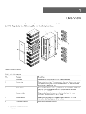
... system fans, one block controller distribution board (BCDB), one block controller (BC), one fan cage, one fan power distribution board (FPDB), and one rear cabinet base. DSS 9000 features No. Bar strip located on rack layout, two different types of delivery may differ from the following illustrations. Feature 1 Bare rack 2 Bus bar top 3 Rear cabinet 4 Bus bar middle 5 Bus bar bottom 6 Side panel (optional) 6 Installation and Service Manual Overview Description Rack mounting enclosure for DSS...
... system fans, one block controller distribution board (BCDB), one block controller (BC), one fan cage, one fan power distribution board (FPDB), and one rear cabinet base. DSS 9000 features No. Bar strip located on rack layout, two different types of delivery may differ from the following illustrations. Feature 1 Bare rack 2 Bus bar top 3 Rear cabinet 4 Bus bar middle 5 Bus bar bottom 6 Side panel (optional) 6 Installation and Service Manual Overview Description Rack mounting enclosure for DSS...

EMC Installation and Service Manual
Page 7
...chassis (one third-width, half-width, and full-width). No. Two switch devices are available to open from left or right, with lock. Reversible front door can be configured to provide networking for power supply units (PSUs). Table 2. Rack specifications Item Height Width Depth Net weight Description Available rack...lb) • 50U: 225.0 kg (496 lb) Installation and Service Manual 7 Overview Feature 7 Block chassis 8 OpenIT bay 9 Power Bay 10 Front door (optional) Rack specifications Description Three types of rack, provides allocated space for the entire system.
...chassis (one third-width, half-width, and full-width). No. Two switch devices are available to open from left or right, with lock. Reversible front door can be configured to provide networking for power supply units (PSUs). Table 2. Rack specifications Item Height Width Depth Net weight Description Available rack...lb) • 50U: 225.0 kg (496 lb) Installation and Service Manual 7 Overview Feature 7 Block chassis 8 OpenIT bay 9 Power Bay 10 Front door (optional) Rack specifications Description Three types of rack, provides allocated space for the entire system.
EMC Installation and Service Manual
Page 8
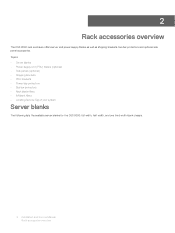
...; Rack blank fillers • IM blank fillers • Locating Service Tag of your system Server blanks The following lists the available server blanks for the DSS 9000: full width, half width, and one third width blank chassis. 8 Installation and Service Manual Rack accessories overview 2 Rack accessories overview The DSS 9000 rack enclosure offers server and power supply blanks as well as shipping brackets, bus bar protectors and optional side panel...
...; Rack blank fillers • IM blank fillers • Locating Service Tag of your system Server blanks The following lists the available server blanks for the DSS 9000: full width, half width, and one third width blank chassis. 8 Installation and Service Manual Rack accessories overview 2 Rack accessories overview The DSS 9000 rack enclosure offers server and power supply blanks as well as shipping brackets, bus bar protectors and optional side panel...
EMC Installation and Service Manual
Page 31
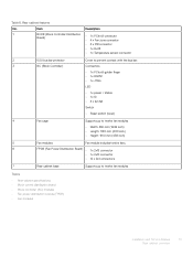
Table 6. Item 1 BCDB (Block Controller Distribution Board) Description • 1 x PCIe x8 connector • 4 x Fan zone connector • 4 x PIB connector • 1 x RJ45 • 1 x Temperature sensor connector 2 0.5U bus bar protector Cover to prevent contact with the bus bar. 3 BC (Block Controller) Connectors • 1 x PCIe x8 golden finger • 1 x RS232 • 1 x JTAG LED • 1 x power / status • 1 x ID • 4 x fan fail Switch • Reset switch (local) 4 Fan cage Supports up to twelve fan modules • Width: 480 mm (18.89...
Table 6. Item 1 BCDB (Block Controller Distribution Board) Description • 1 x PCIe x8 connector • 4 x Fan zone connector • 4 x PIB connector • 1 x RJ45 • 1 x Temperature sensor connector 2 0.5U bus bar protector Cover to prevent contact with the bus bar. 3 BC (Block Controller) Connectors • 1 x PCIe x8 golden finger • 1 x RS232 • 1 x JTAG LED • 1 x power / status • 1 x ID • 4 x fan fail Switch • Reset switch (local) 4 Fan cage Supports up to twelve fan modules • Width: 480 mm (18.89...

EMC Installation and Service Manual
Page 37
... (W x L x H) Connector Switch Net weight Operating voltage/current LED definition Table 11. Infrastructure mismatch Identify BC board location Fan fail Normal work Installation and Service Manual 37 Rear cabinet overview LED definition LED Power/Status Color Green Amber UID Fan zone 1~2 Blue Amber Description 120 mm x 24 mm x 88 mm (4.72 inch x 0.94 inch x 3.46 inch) • 1 x PCIe x8 golden finger • 1 x RS232 • 1 x JTAG 1 x Reset SW (Local) 127.2 g (4.49 ounce) 3.3 V, current 1 A Status On On Blinking...
... (W x L x H) Connector Switch Net weight Operating voltage/current LED definition Table 11. Infrastructure mismatch Identify BC board location Fan fail Normal work Installation and Service Manual 37 Rear cabinet overview LED definition LED Power/Status Color Green Amber UID Fan zone 1~2 Blue Amber Description 120 mm x 24 mm x 88 mm (4.72 inch x 0.94 inch x 3.46 inch) • 1 x PCIe x8 golden finger • 1 x RS232 • 1 x JTAG 1 x Reset SW (Local) 127.2 g (4.49 ounce) 3.3 V, current 1 A Status On On Blinking...

EMC Installation and Service Manual
Page 43
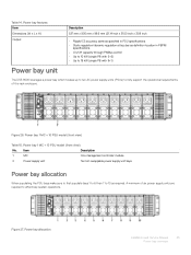
...way fan speed and power status and operational event information. Power bay power module regulates power control for the power bay chassis. Ten hot-swappable power supply units. Four RJ45 connectors, one 1x5 connector, one 1x6 connector and one 2x8 connector. Includes rack manager board (RMB) and infrastructure module (IM). Installation and Service Manual 43 Power bay overview Item 1 Top cover 2 Bus Bar PB 3 PBPM 4 Rear IO module 5 DSS 9000 rack manager module 6 Power supply unit (PSU) 7 Management controller module Topics: • Power bay specifications...
...way fan speed and power status and operational event information. Power bay power module regulates power control for the power bay chassis. Ten hot-swappable power supply units. Four RJ45 connectors, one 1x5 connector, one 1x6 connector and one 2x8 connector. Includes rack manager board (RMB) and infrastructure module (IM). Installation and Service Manual 43 Power bay overview Item 1 Top cover 2 Bus Bar PB 3 PBPM 4 Rear IO module 5 DSS 9000 rack manager module 6 Power supply unit (PSU) 7 Management controller module Topics: • Power bay specifications...
EMC Installation and Service Manual
Page 45
... (single PB with 9+1) The DSS 9000 leverages a power bay which houses up to ten AC power supply units (PSUs) to fully support the operational requirements of six power supply units are required to 10 as definition location in PSU specifications • Static regulation/dynamic regulation at bus bar as required. Item Description 1 MC One management controller module 2 Power supply unit Ten hot-swappable power supply unit bays Power bay allocation When populating the...
... (single PB with 9+1) The DSS 9000 leverages a power bay which houses up to ten AC power supply units (PSUs) to fully support the operational requirements of six power supply units are required to 10 as definition location in PSU specifications • Static regulation/dynamic regulation at bus bar as required. Item Description 1 MC One management controller module 2 Power supply unit Ten hot-swappable power supply unit bays Power bay allocation When populating the...

EMC Installation and Service Manual
Page 53
... socket • 1 x USB • 1 x JTAG • 1 x Battery holder 1 x Power Button 12 V, current 1.3 A Status On On Blinking On On On/Off/Blinking On Blinking On Description 1G LAN speed 10M/100M LAN speed Traffic access Power on Power on fail Identify MC board location If there is no error Infrastructure mismatch Link between MC and IM is Absent Installation and Service Manual 53 Power bay overview Table 21. Management controller Item Board length Board width Net Weight Connector Switch Operating voltage/current LED definition Table...
... socket • 1 x USB • 1 x JTAG • 1 x Battery holder 1 x Power Button 12 V, current 1.3 A Status On On Blinking On On On/Off/Blinking On Blinking On Description 1G LAN speed 10M/100M LAN speed Traffic access Power on Power on fail Identify MC board location If there is no error Infrastructure mismatch Link between MC and IM is Absent Installation and Service Manual 53 Power bay overview Table 21. Management controller Item Board length Board width Net Weight Connector Switch Operating voltage/current LED definition Table...

EMC Installation and Service Manual
Page 56
DSS 9000 rack manager module Figure 33. DSS 9000 rack manager module Table 25. DSS 9000 rack manager module features Item Board length Description 323.25 mm (12.73 inch) Board width 242.3 mm (9.54 inch) Net Weight 1,050 g (37.03 ounce) Connector • 2 x 8-port RJ45 • 1 x 2-port RJ45 • 1 x (2x2) Power connector • 1 x USB • 1 x (1x5) connector • 1 x Micro USB Switch Operating voltage/current 1 x Reset Button 12 V, current 2 A Infrastructure module LED definition 56 Installation and Service Manual Power bay overview
DSS 9000 rack manager module Figure 33. DSS 9000 rack manager module Table 25. DSS 9000 rack manager module features Item Board length Description 323.25 mm (12.73 inch) Board width 242.3 mm (9.54 inch) Net Weight 1,050 g (37.03 ounce) Connector • 2 x 8-port RJ45 • 1 x 2-port RJ45 • 1 x (2x2) Power connector • 1 x USB • 1 x (1x5) connector • 1 x Micro USB Switch Operating voltage/current 1 x Reset Button 12 V, current 2 A Infrastructure module LED definition 56 Installation and Service Manual Power bay overview

EMC Installation and Service Manual
Page 57
... or fan fault Identify IM board location Active Link speed: 1Gb No link Active Link speed: 100Mb Link speed: 10Mb or no link Active Link speed: 1Gb Link speed: Other No link Installation and Service Manual 57 Power bay overview LED definition Item Port 1 Mgmt LED Right LED Left LED 2 Power/Status 3 UID 4 Block (1-10) Right LED Left LED 5 PB (1-4) Right LED Left LED 6 Gb (1-4) Right LED Left LED Color Green Green Yellow Green Amber Blue Green Green Green Yellow Green Green Yellow Status Blinking On On...
... or fan fault Identify IM board location Active Link speed: 1Gb No link Active Link speed: 100Mb Link speed: 10Mb or no link Active Link speed: 1Gb Link speed: Other No link Installation and Service Manual 57 Power bay overview LED definition Item Port 1 Mgmt LED Right LED Left LED 2 Power/Status 3 UID 4 Block (1-10) Right LED Left LED 5 PB (1-4) Right LED Left LED 6 Gb (1-4) Right LED Left LED Color Green Green Yellow Green Amber Blue Green Green Green Yellow Green Green Yellow Status Blinking On On...
EMC Installation and Service Manual
Page 71
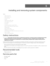
...8226; Safety instructions • Recommended tools • Service parts list • Servers • Hard disk drive (HDD) trays • Power supply units (PSU) • Fan modules • Fan blocks • Fan power distribution boards (FPDB) • Block Controller Distribution Board (BCDB) • Installing BCDB • Block controllers (BC) • Management controllers (MC) • Rack manager board (RMB) and infrastructure module (IM) • Rear IO modules • Power interface board (PIB) Safety instructions CAUTION: Many repairs may only be done by the edges, ensuring not...
...8226; Safety instructions • Recommended tools • Service parts list • Servers • Hard disk drive (HDD) trays • Power supply units (PSU) • Fan modules • Fan blocks • Fan power distribution boards (FPDB) • Block Controller Distribution Board (BCDB) • Installing BCDB • Block controllers (BC) • Management controllers (MC) • Rack manager board (RMB) and infrastructure module (IM) • Rear IO modules • Power interface board (PIB) Safety instructions CAUTION: Many repairs may only be done by the edges, ensuring not...

EMC Installation and Service Manual
Page 72
PSU blank - Half width server blank - MC - Rear I/O - Steps 1 Press the release latches on the side of the server. 2 Slide the server out of the block. 72 Installation and Service Manual Installing and removing system components PBPM • Mechanical - Infrastructure module - BC Servers Removing one third-width server Prerequisite 1 Ensure that you read the Safety instructions. - Full width server blank • PCBA module - DSS 9000 rack manager module - Third width server blank - MC cover - PSU -
PSU blank - Half width server blank - MC - Rear I/O - Steps 1 Press the release latches on the side of the server. 2 Slide the server out of the block. 72 Installation and Service Manual Installing and removing system components PBPM • Mechanical - Infrastructure module - BC Servers Removing one third-width server Prerequisite 1 Ensure that you read the Safety instructions. - Full width server blank • PCBA module - DSS 9000 rack manager module - Third width server blank - MC cover - PSU -

EMC Installation and Service Manual
Page 90
Power supply units (PSU) 90 Installation and Service Manual Installing and removing system components For more details, see Installing full-width server. 7 Install the full width server.
Power supply units (PSU) 90 Installation and Service Manual Installing and removing system components For more details, see Installing full-width server. 7 Install the full width server.
EMC Installation and Service Manual
Page 139
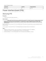
... instructions. Log in 2 minutes. Installation and Service Manual 139 Installing and removing system components Damage due to servicing that is not authorized is turned off. Steps 1 Make sure the system is not covered by warranty. The command line interface (CLI) is fully completed in to service any part of the Power Interface Board (PIB), make sure the power source and power cables are turned off the system. The turn-off process is displayed. 2 Change...
... instructions. Log in 2 minutes. Installation and Service Manual 139 Installing and removing system components Damage due to servicing that is not authorized is turned off. Steps 1 Make sure the system is not covered by warranty. The command line interface (CLI) is fully completed in to service any part of the Power Interface Board (PIB), make sure the power source and power cables are turned off the system. The turn-off process is displayed. 2 Change...
EMC Installation and Service Manual
Page 149
... following procedure is turned off process is displayed. If the system is not covered by a certified service technician. Steps 1 Make sure the system is provided as reference information only. c Type the command Stop to service any part of the Power Interface Board (PIB), make sure the power source and power cables are turned off the system. The turn off and disconnected. Installation and Service Manual 149 Installing and removing system components...
... following procedure is turned off process is displayed. If the system is not covered by a certified service technician. Steps 1 Make sure the system is provided as reference information only. c Type the command Stop to service any part of the Power Interface Board (PIB), make sure the power source and power cables are turned off the system. The turn off and disconnected. Installation and Service Manual 149 Installing and removing system components...
EMC Installation and Service Manual
Page 160
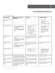
.... 160 Installation and Service Manual Troubleshooting list LED will blink on every 1s interval and 'LastUpgradeStatus' property on 100% PWM. • If 1 fan fails, BC will move to fan table C. 1 or more than 1 fans become absent from right group of 6 fans • If 2 fan fails, BC will move to (fan no HW damage. Troubleshooting step 1 Check HTPB. 2 Check G5.5 FW version in IM/MC/BC. 3 Check "llcDebug" command. 1 Ensure fan table and...
.... 160 Installation and Service Manual Troubleshooting list LED will blink on every 1s interval and 'LastUpgradeStatus' property on 100% PWM. • If 1 fan fails, BC will move to fan table C. 1 or more than 1 fans become absent from right group of 6 fans • If 2 fan fails, BC will move to (fan no HW damage. Troubleshooting step 1 Check HTPB. 2 Check G5.5 FW version in IM/MC/BC. 3 Check "llcDebug" command. 1 Ensure fan table and...

EMC Installation and Service Manual
Page 161
... release. G5.5. Ask if the FW is down. MC will dump log in llcEvent.log file. Troubleshooting step Ensure LAN connection is wrong (header/ and MC will not lit Amber LED). Call Dell help. Installation and Service Manual 161 Troubleshooting list Issue description MC Error LED amber PSU status LED amber G5.5 FW update fail Some server can not boot after rack power on Trigger event for amber LED (MC/IM/BC) Root cause MC will send PSU...
... release. G5.5. Ask if the FW is down. MC will dump log in llcEvent.log file. Troubleshooting step Ensure LAN connection is wrong (header/ and MC will not lit Amber LED). Call Dell help. Installation and Service Manual 161 Troubleshooting list Issue description MC Error LED amber PSU status LED amber G5.5 FW update fail Some server can not boot after rack power on Trigger event for amber LED (MC/IM/BC) Root cause MC will send PSU...
EMC DSS 9000 RackManager User Guide
Page 12
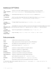
... to use https: (Note: doesn't stop rhost from redirect http to execute raw http methods(GET,PATCH,POST...) and URIs For Subcommand usage, options, operations, help: RMredfishtool -h -- operations on Computer Systems in the /Chassis collection Managers -- Specify the request header list--overrides defaults. redfishtool hello world subcommand for dev testing about this version of RMredfishtool versions -- Flag for specific subcommand 12 Example Utilities...
... to use https: (Note: doesn't stop rhost from redirect http to execute raw http methods(GET,PATCH,POST...) and URIs For Subcommand usage, options, operations, help: RMredfishtool -h -- operations on Computer Systems in the /Chassis collection Managers -- Specify the request header list--overrides defaults. redfishtool hello world subcommand for dev testing about this version of RMredfishtool versions -- Flag for specific subcommand 12 Example Utilities...

