
System Information Guide
Page 13
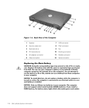
... connector 7 USB connector 8 PS/2 connector 9 Fan 10 Docking connector 11 Parallel connector 12 Serial connector Replacing the Main Battery CAUTION: Using the wrong battery type may present a risk of fire or explosion. If you install a NiMH battery, the battery status lights blink alternately green and amber. 1-10 Dell Latitude System Information (Rev. 11/3/98...
... connector 7 USB connector 8 PS/2 connector 9 Fan 10 Docking connector 11 Parallel connector 12 Serial connector Replacing the Main Battery CAUTION: Using the wrong battery type may present a risk of fire or explosion. If you install a NiMH battery, the battery status lights blink alternately green and amber. 1-10 Dell Latitude System Information (Rev. 11/3/98...

Service Manual
Page 1
... Dell™ Latitude™ C600/C500 Series Service Manual Before You Begin Preparing to Work Inside the Computer Recommended Tools Screw Identification Removing and Replacing Parts Components Hard Drive Memory Module Mini-PCI Card Assembly Keyboard Assembly Removing the Display Assembly Display Assembly Latch Hinge Covers Palmrest Assembly Microprocessor Thermal Cooling Assembly Hybrid Cooling Fan...
... Dell™ Latitude™ C600/C500 Series Service Manual Before You Begin Preparing to Work Inside the Computer Recommended Tools Screw Identification Removing and Replacing Parts Components Hard Drive Memory Module Mini-PCI Card Assembly Keyboard Assembly Removing the Display Assembly Display Assembly Latch Hinge Covers Palmrest Assembly Microprocessor Thermal Cooling Assembly Hybrid Cooling Fan...
Service Manual
Page 8
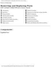
Removing and Replacing Parts : Dell Latitude C600/C500 Series Service Manual Back to Contents Page Removing and Replacing Parts Dell™ Latitude™ C600/C500 Series Service Manual Components Hard Drive Memory Module Mini-PCI Card Assembly Keyboard Assembly Removing the Display Assembly Display Assembly Latch Hinge Covers Palmrest Assembly Microprocessor Thermal Cooling Assembly Hybrid Cooling Fan Microprocessor Module Reserve...
Removing and Replacing Parts : Dell Latitude C600/C500 Series Service Manual Back to Contents Page Removing and Replacing Parts Dell™ Latitude™ C600/C500 Series Service Manual Components Hard Drive Memory Module Mini-PCI Card Assembly Keyboard Assembly Removing the Display Assembly Display Assembly Latch Hinge Covers Palmrest Assembly Microprocessor Thermal Cooling Assembly Hybrid Cooling Fan Microprocessor Module Reserve...

Service Manual
Page 35
Remove the hard drive. file:///F|/Service%20Manuals/Dell/Latitude/c500-600/remove.htm (28 of the computer, and place it forward toward the front of 40) [2/28/2004 7:53:33 AM] Turn the computer ... the system board assembly. Remove the microprocessor thermal cooling assembly from 1 to 4. Loosen the four captive screws securing the microprocessor thermal cooling assembly. 5. Removing and Replacing Parts : Dell Latitude C600/C500 Series Service Manual 3. Hybrid Cooling Fan Hybrid Cooling Fan Removing the Hybrid Cooling...
Remove the hard drive. file:///F|/Service%20Manuals/Dell/Latitude/c500-600/remove.htm (28 of the computer, and place it forward toward the front of 40) [2/28/2004 7:53:33 AM] Turn the computer ... the system board assembly. Remove the microprocessor thermal cooling assembly from 1 to 4. Loosen the four captive screws securing the microprocessor thermal cooling assembly. 5. Removing and Replacing Parts : Dell Latitude C600/C500 Series Service Manual 3. Hybrid Cooling Fan Hybrid Cooling Fan Removing the Hybrid Cooling...

Service Manual
Page 36
...that secure the hybrid cooling fan to prevent intermittent contact between the cam screw and microprocessor. Microprocessor Module Microprocessor Modules NOTICE: Hold the microprocessor down while turning the cam screw to the system board. 7. NOTE: The fan power cable is long, and...] Remove the palmrest assembly. 5. Remove the keyboard assembly. 3. Remove the display assembly. 4. Removing and Replacing Parts : Dell Latitude C600/C500 Series Service Manual 2. Disconnect the fan power cable from under the EMI shield to provide access to the connector. NOTICE: Do not block the ...
...that secure the hybrid cooling fan to prevent intermittent contact between the cam screw and microprocessor. Microprocessor Module Microprocessor Modules NOTICE: Hold the microprocessor down while turning the cam screw to the system board. 7. NOTE: The fan power cable is long, and...] Remove the palmrest assembly. 5. Remove the keyboard assembly. 3. Remove the display assembly. 4. Removing and Replacing Parts : Dell Latitude C600/C500 Series Service Manual 2. Disconnect the fan power cable from under the EMI shield to provide access to the connector. NOTICE: Do not block the ...

Service Manual
Page 43
Removing and Replacing Parts : Dell Latitude C600/C500 Series Service Manual Removing the System Board NOTICE: Disconnect the computer and any ...Card ejectors do not extend from electrical outlets, and remove any installed batteries. NOTICE: Read "Preparing to the file:///F|/Service%20Manuals/Dell/Latitude/c500-600/remove.htm (36 of 40) [2/28/2004 7:53:33 AM] Remove the microprocessor. 7. Turn the computer over.... 10. Remove the three M2.5 x 5-mm screws labeled with a "circle B" that secure the fan guard to Work Inside the Computer" before performing the following procedure. 1.
Removing and Replacing Parts : Dell Latitude C600/C500 Series Service Manual Removing the System Board NOTICE: Disconnect the computer and any ...Card ejectors do not extend from electrical outlets, and remove any installed batteries. NOTICE: Read "Preparing to the file:///F|/Service%20Manuals/Dell/Latitude/c500-600/remove.htm (36 of 40) [2/28/2004 7:53:33 AM] Remove the microprocessor. 7. Turn the computer over.... 10. Remove the three M2.5 x 5-mm screws labeled with a "circle B" that secure the fan guard to Work Inside the Computer" before performing the following procedure. 1.

Service Manual
Page 44
... 13. The fan guard is identified by a white "circle B" and arrow on a red label attached to the top of the battery connector on the front center of the bottom case assembly. Remove the speakers from the bottom case assembly. Install the replacement system board. ...the bottom case assembly over and remove the M2.5 x 5-mm screw, which is located on the replacement system board. 2. Replacing the System Board 1. System Board Assembly 11. Removing and Replacing Parts : Dell Latitude C600/C500 Series Service Manual bottom case assembly. a. Pull the right side of 40) [2/28/2004 7:...
... 13. The fan guard is identified by a white "circle B" and arrow on a red label attached to the top of the battery connector on the front center of the bottom case assembly. Remove the speakers from the bottom case assembly. Install the replacement system board. ...the bottom case assembly over and remove the M2.5 x 5-mm screw, which is located on the replacement system board. 2. Replacing the System Board 1. System Board Assembly 11. Removing and Replacing Parts : Dell Latitude C600/C500 Series Service Manual bottom case assembly. a. Pull the right side of 40) [2/28/2004 7:...

Service Manual
Page 45
..., be crimped or pinched when the complete assembly is put back together. 5. Removing and Replacing Parts : Dell Latitude C600/C500 Series Service Manual b. Replace the fan guard cover, inserting the tab into the BIOS of the replacement system board assembly. If you replace the screw opposite the tab first, it makes it easier to enter the system's service...
..., be crimped or pinched when the complete assembly is put back together. 5. Removing and Replacing Parts : Dell Latitude C600/C500 Series Service Manual b. Replace the fan guard cover, inserting the tab into the BIOS of the replacement system board assembly. If you replace the screw opposite the tab first, it makes it easier to enter the system's service...


