
System Information Guide
Page 13
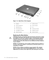
... amber. 1-10 Dell Latitude System Information (Rev. 11/3/98) FILE LOCATION: D:\Eri_DProject\Dell\Temp\413CU0s\413CUeb0.fm Figure 1-6. Back View of the Computer 1 Speaker 2 Security cable slot 3 Hard-disk drive 4 PC Card slots (2) 5 AC adapter connector 6 Video connector 7 USB connector 8 PS/2 connector 9 Fan 10 Docking connector 11 Parallel connector 12 Serial connector Replacing the Main...
... amber. 1-10 Dell Latitude System Information (Rev. 11/3/98) FILE LOCATION: D:\Eri_DProject\Dell\Temp\413CU0s\413CUeb0.fm Figure 1-6. Back View of the Computer 1 Speaker 2 Security cable slot 3 Hard-disk drive 4 PC Card slots (2) 5 AC adapter connector 6 Video connector 7 USB connector 8 PS/2 connector 9 Fan 10 Docking connector 11 Parallel connector 12 Serial connector Replacing the Main...

Service Manual
Page 1
...or loss of data and tells you how to Work Inside the Computer Recommended Tools Screw Identification Removing and Replacing Parts Components Hard Drive Memory Module Mini-PCI Card Assembly Keyboard Assembly Removing the Display Assembly Display Assembly ...Fan Microprocessor Module Reserve Battery Speaker Assemblies System Board Assembly Battery and Modular Bay Latch Assemblies Notes, Notices, and Cautions NOTE: A NOTE indicates important information that helps you make better use of 2) [2/28/2004 7:53:17 AM] Dell Latitude C600/C500 Series Service Manual Dell™ Latitude™ C600...
...or loss of data and tells you how to Work Inside the Computer Recommended Tools Screw Identification Removing and Replacing Parts Components Hard Drive Memory Module Mini-PCI Card Assembly Keyboard Assembly Removing the Display Assembly Display Assembly ...Fan Microprocessor Module Reserve Battery Speaker Assemblies System Board Assembly Battery and Modular Bay Latch Assemblies Notes, Notices, and Cautions NOTE: A NOTE indicates important information that helps you make better use of 2) [2/28/2004 7:53:17 AM] Dell Latitude C600/C500 Series Service Manual Dell™ Latitude™ C600...
Service Manual
Page 8
Removing and Replacing Parts : Dell Latitude C600/C500 Series Service Manual Back to Contents Page Removing and Replacing Parts Dell™ Latitude™ C600/C500 Series Service Manual Components Hard Drive Memory Module Mini-PCI Card Assembly Keyboard Assembly Removing the Display Assembly Display Assembly Latch Hinge Covers Palmrest Assembly Microprocessor Thermal Cooling Assembly Hybrid Cooling Fan Microprocessor Module Reserve...
Removing and Replacing Parts : Dell Latitude C600/C500 Series Service Manual Back to Contents Page Removing and Replacing Parts Dell™ Latitude™ C600/C500 Series Service Manual Components Hard Drive Memory Module Mini-PCI Card Assembly Keyboard Assembly Removing the Display Assembly Display Assembly Latch Hinge Covers Palmrest Assembly Microprocessor Thermal Cooling Assembly Hybrid Cooling Fan Microprocessor Module Reserve...

Service Manual
Page 35
... NOTICE: When reattaching the microprocessor thermal cooling assembly, tighten the captive screws in consecutive order, from the system board assembly. file:///F|/Service%20Manuals/Dell/Latitude/c500-600/remove.htm (28 of the computer, and place it forward toward the front of 40) [2/28/2004 7:53:33 AM] ... it face down on the palmrest. 4. Remove the microprocessor thermal cooling assembly from 1 to 4. Remove the hard drive. Hybrid Cooling Fan Hybrid Cooling Fan Removing the Hybrid Cooling Fan 1. Removing and Replacing Parts : Dell Latitude C600/C500 Series Service Manual 3.
... NOTICE: When reattaching the microprocessor thermal cooling assembly, tighten the captive screws in consecutive order, from the system board assembly. file:///F|/Service%20Manuals/Dell/Latitude/c500-600/remove.htm (28 of the computer, and place it forward toward the front of 40) [2/28/2004 7:53:33 AM] ... it face down on the palmrest. 4. Remove the microprocessor thermal cooling assembly from 1 to 4. Remove the hard drive. Hybrid Cooling Fan Hybrid Cooling Fan Removing the Hybrid Cooling Fan 1. Removing and Replacing Parts : Dell Latitude C600/C500 Series Service Manual 3.

Service Manual
Page 36
... board interface connector and remove the hybrid cooling fan. file:///F|/Service%20Manuals/Dell/Latitude/c500-600/remove.htm (29 of 40) [2/28/2004 7:53:33 AM] Remove the palmrest assembly. 5. Removing and Replacing Parts : Dell Latitude C600/C500 Series Service Manual 2. Remove the thermal cooling... assembly. 6. Remove the two M2.5 x 5-mm screws and one M2 x 3-mm screw that secure the hybrid cooling fan to the system board. 7. Remove the ...
... board interface connector and remove the hybrid cooling fan. file:///F|/Service%20Manuals/Dell/Latitude/c500-600/remove.htm (29 of 40) [2/28/2004 7:53:33 AM] Remove the palmrest assembly. 5. Removing and Replacing Parts : Dell Latitude C600/C500 Series Service Manual 2. Remove the thermal cooling... assembly. 6. Remove the two M2.5 x 5-mm screws and one M2 x 3-mm screw that secure the hybrid cooling fan to the system board. 7. Remove the ...

Service Manual
Page 43
...plastic blanks are removed from electrical outlets, and remove any installed batteries. Remove the display assembly. 4. Removing and Replacing Parts : Dell Latitude C600/C500 Series Service Manual Removing the System Board NOTICE: Disconnect the computer and any attached devices from the PC ...Card slot. 8. Remove the three M2.5 x 5-mm screws labeled with a "circle B" that secure the fan guard to the file:///F|/Service%20Manuals/Dell/Latitude...
...plastic blanks are removed from electrical outlets, and remove any installed batteries. Remove the display assembly. 4. Removing and Replacing Parts : Dell Latitude C600/C500 Series Service Manual Removing the System Board NOTICE: Disconnect the computer and any attached devices from the PC ...Card slot. 8. Remove the three M2.5 x 5-mm screws labeled with a "circle B" that secure the fan guard to the file:///F|/Service%20Manuals/Dell/Latitude...

Service Manual
Page 44
...from the system board assembly as you simultaneously lift the front of the bottom case assembly. a. Removing and Replacing Parts : Dell Latitude C600/C500 Series Service Manual bottom case assembly. Remove the speakers from the bottom case assembly. Insert the external ...replacement system board. file:///F|/Service%20Manuals/Dell/Latitude/c500-600/remove.htm (37 of bottom case assembly, next to the replacement system board. 3. Install the microprocessor on the front center of the battery connector on the replacement system board. 2. System Board Assembly 11. The fan...
...from the system board assembly as you simultaneously lift the front of the bottom case assembly. a. Removing and Replacing Parts : Dell Latitude C600/C500 Series Service Manual bottom case assembly. Remove the speakers from the bottom case assembly. Insert the external ...replacement system board. file:///F|/Service%20Manuals/Dell/Latitude/c500-600/remove.htm (37 of bottom case assembly, next to the replacement system board. 3. Install the microprocessor on the front center of the battery connector on the replacement system board. 2. System Board Assembly 11. The fan...

Service Manual
Page 45
... Latch Assemblies file:///F|/Service%20Manuals/Dell/Latitude/c500-600/remove.htm (38 of the replacement system board assembly. Replace the nine M2.5 x 5-mm screws, starting on the computer. NOTE: Be sure to route cables so that accompanied the replacement system board assembly into the ... the PC Card slot. 7. Replace the palmrest assembly, the display assembly, the keyboard assembly, and the hard drive. 6. Replace the fan guard cover, inserting the tab into the BIOS of 40) [2/28/2004 7:53:33 AM] Removing and Replacing Parts : Dell Latitude C600/C500 Series Service Manual b. c....
... Latch Assemblies file:///F|/Service%20Manuals/Dell/Latitude/c500-600/remove.htm (38 of the replacement system board assembly. Replace the nine M2.5 x 5-mm screws, starting on the computer. NOTE: Be sure to route cables so that accompanied the replacement system board assembly into the ... the PC Card slot. 7. Replace the palmrest assembly, the display assembly, the keyboard assembly, and the hard drive. 6. Replace the fan guard cover, inserting the tab into the BIOS of 40) [2/28/2004 7:53:33 AM] Removing and Replacing Parts : Dell Latitude C600/C500 Series Service Manual b. c....


