

Service Manual
Page 1
.... file:///F|/Service%20Manuals/Dell/Latitude/c500-600/index.htm (1 of data and tells you make better use of your computer. Dell Latitude C600/C500 Series Service Manual Dell™ Latitude™ C600/C500 Series Service Manual... Before You Begin Preparing to Work Inside the Computer Recommended Tools Screw Identification Removing and Replacing Parts Components Hard Drive Memory Module Mini-PCI Card Assembly Keyboard Assembly Removing the Display Assembly Display Assembly Latch Hinge...
.... file:///F|/Service%20Manuals/Dell/Latitude/c500-600/index.htm (1 of data and tells you make better use of your computer. Dell Latitude C600/C500 Series Service Manual Dell™ Latitude™ C600/C500 Series Service Manual... Before You Begin Preparing to Work Inside the Computer Recommended Tools Screw Identification Removing and Replacing Parts Components Hard Drive Memory Module Mini-PCI Card Assembly Keyboard Assembly Removing the Display Assembly Display Assembly Latch Hinge...

Service Manual
Page 5
Before You Begin : Dell Latitude C600/C500 Series Service Manual NOTICE: When reinstalling a screw, you must use a screw of 6) [2/28/2004 7:53:27 AM] Make sure that the screw is properly aligned with its corresponding hole, and avoid overtightening. Screw Placement Hard Drive Door Security: (1 each) Keyboard to Bottom Case Assembly: (5 each) Display Assembly Bezel: (6 each) Display Assembly Hinge Bracket to Bottom Case Assembly: (5 each) Rubber Screw Covers (6 each) file:///F|/Service%20Manuals/Dell/Latitude/c500-600/begin.htm (4 of the correct diameter and length.
Before You Begin : Dell Latitude C600/C500 Series Service Manual NOTICE: When reinstalling a screw, you must use a screw of 6) [2/28/2004 7:53:27 AM] Make sure that the screw is properly aligned with its corresponding hole, and avoid overtightening. Screw Placement Hard Drive Door Security: (1 each) Keyboard to Bottom Case Assembly: (5 each) Display Assembly Bezel: (6 each) Display Assembly Hinge Bracket to Bottom Case Assembly: (5 each) Rubber Screw Covers (6 each) file:///F|/Service%20Manuals/Dell/Latitude/c500-600/begin.htm (4 of the correct diameter and length.
Service Manual
Page 8
... Series Service Manual Back to Contents Page Removing and Replacing Parts Dell™ Latitude™ C600/C500 Series Service Manual Components Hard Drive Memory Module Mini-PCI Card Assembly Keyboard Assembly Removing the Display Assembly Display Assembly Latch Hinge Covers Palmrest Assembly Microprocessor Thermal Cooling Assembly Hybrid Cooling Fan Microprocessor Module Reserve Battery Speaker...
... Series Service Manual Back to Contents Page Removing and Replacing Parts Dell™ Latitude™ C600/C500 Series Service Manual Components Hard Drive Memory Module Mini-PCI Card Assembly Keyboard Assembly Removing the Display Assembly Display Assembly Latch Hinge Covers Palmrest Assembly Microprocessor Thermal Cooling Assembly Hybrid Cooling Fan Microprocessor Module Reserve Battery Speaker...

Service Manual
Page 18
...from electrical outlets, and remove any installed batteries. Removing and Replacing Parts : Dell Latitude C600/C500 Series Service Manual 4. NOTE: Always remove and replace the display panel as a complete assembly. Display Assembly file:///F|/Service%20Manuals/Dell/Latitude/c500-600/remove.htm (11 of the palmrest. 5. NOTICE: Read "Preparing...yourself by using a wrist grounding strap or by touching an unpainted metal surface on the computer. the display assembly hinges pass through the back of the palmrest assembly. Reinstall the five M2.5 x 12-mm screws in the holes labeled "circle K."
...from electrical outlets, and remove any installed batteries. Removing and Replacing Parts : Dell Latitude C600/C500 Series Service Manual 4. NOTE: Always remove and replace the display panel as a complete assembly. Display Assembly file:///F|/Service%20Manuals/Dell/Latitude/c500-600/remove.htm (11 of the palmrest. 5. NOTICE: Read "Preparing...yourself by using a wrist grounding strap or by touching an unpainted metal surface on the computer. the display assembly hinges pass through the back of the palmrest assembly. Reinstall the five M2.5 x 12-mm screws in the holes labeled "circle K."

Service Manual
Page 19
...Dell Latitude C600/C500 Series Service Manual 1. a. From the back of the center control cover and pry it does not open past this position. 6. Close the display. 4. Use a scribe to the system board assembly. 7. b. Remove the two M2 x 3-mm screws that covers the display-feed flex cable file:///F|/Service%20Manuals/Dell/Latitude...the display assembly so it loose from the bottom case assembly. 3. There are two screws on the right hinge and three screws on the left hinge. 5. Remove the hard drive. 2. Remove the flex cable EMI shield retention bracket that secure the EMI ...
...Dell Latitude C600/C500 Series Service Manual 1. a. From the back of the center control cover and pry it does not open past this position. 6. Close the display. 4. Use a scribe to the system board assembly. 7. b. Remove the two M2 x 3-mm screws that covers the display-feed flex cable file:///F|/Service%20Manuals/Dell/Latitude...the display assembly so it loose from the bottom case assembly. 3. There are two screws on the right hinge and three screws on the left hinge. 5. Remove the hard drive. 2. Remove the flex cable EMI shield retention bracket that secure the EMI ...

Service Manual
Page 22
... through the black plastic flex cable retention bracket (see "14.1-Inch Display Assembly Bezel and Panel"). 7. Remove the hard drive. 2. Remove the hinge covers. 5. Use the scribe to the bezel, do not bend the bezel while separating it from the display-assembly top cover and inverter connector ...pulling straight up on the front of the screw holes located on the bezel on the attached pull tab. 8. Removing and Replacing Parts : Dell Latitude C600/C500 Series Service Manual 1. Remove the display assembly. 3. NOTICE: To avoid damage to pry the six rubber screw covers out of the display...
... through the black plastic flex cable retention bracket (see "14.1-Inch Display Assembly Bezel and Panel"). 7. Remove the hard drive. 2. Remove the hinge covers. 5. Use the scribe to the bezel, do not bend the bezel while separating it from the display-assembly top cover and inverter connector ...pulling straight up on the front of the screw holes located on the bezel on the attached pull tab. 8. Removing and Replacing Parts : Dell Latitude C600/C500 Series Service Manual 1. Remove the display assembly. 3. NOTICE: To avoid damage to pry the six rubber screw covers out of the display...
Service Manual
Page 25
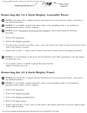
... six rubber screw covers out of the display assembly. 4. Remove the hard drive. 2. Remove the display assembly bezel. 4. file:///F|/Service%20Manuals/Dell/Latitude/c500-600/remove.htm (18 of the display assembly. Remove the hard drive. 2. Remove the four M3 x 3-mm screws on the computer...scribe to the support bracket. Remove the hinge covers. 5. Remove the six M2.5 x 5-mm screws located on the bezel on the front of 40) [2/28/2004 7:53:33 AM] Remove the display assembly. 3. Removing and Replacing Parts : Dell Latitude C600/C500 Series Service Manual Removing the 12.1-...
... six rubber screw covers out of the display assembly. 4. Remove the hard drive. 2. Remove the display assembly bezel. 4. file:///F|/Service%20Manuals/Dell/Latitude/c500-600/remove.htm (18 of the display assembly. Remove the hard drive. 2. Remove the four M3 x 3-mm screws on the computer...scribe to the support bracket. Remove the hinge covers. 5. Remove the six M2.5 x 5-mm screws located on the bezel on the front of 40) [2/28/2004 7:53:33 AM] Remove the display assembly. 3. Removing and Replacing Parts : Dell Latitude C600/C500 Series Service Manual Removing the 12.1-...

Service Manual
Page 29
If the latch is damaged, replace the display-assembly top cover. Removing and Replacing Parts : Dell Latitude C600/C500 Series Service Manual NOTICE: Do not remove the display assembly latch from 14.1-inch SXGA+ and 12.1-inch display panels. Hinge Covers Removing the Hinge Covers Removing the Hinge Covers file:///F|/Service%20Manuals/Dell/Latitude/c500-600/remove.htm (22 of 40) [2/28/2004 7:53:33 AM]
If the latch is damaged, replace the display-assembly top cover. Removing and Replacing Parts : Dell Latitude C600/C500 Series Service Manual NOTICE: Do not remove the display assembly latch from 14.1-inch SXGA+ and 12.1-inch display panels. Hinge Covers Removing the Hinge Covers Removing the Hinge Covers file:///F|/Service%20Manuals/Dell/Latitude/c500-600/remove.htm (22 of 40) [2/28/2004 7:53:33 AM]

Service Manual
Page 30
Replacing the Hinge Covers Hinge Covers file:///F|/Service%20Manuals/Dell/Latitude/c500-600/remove.htm (23 of the hinges. To remove the hinge covers, slide them off of 40) [2/28/2004 7:53:33 AM] Rotate the hinges forward at an angle of approximately 90 degrees to the front of the display assembly. 3. Remove the display assembly. 2. Removing and Replacing Parts : Dell Latitude C600/C500 Series Service Manual 1.
Replacing the Hinge Covers Hinge Covers file:///F|/Service%20Manuals/Dell/Latitude/c500-600/remove.htm (23 of the hinges. To remove the hinge covers, slide them off of 40) [2/28/2004 7:53:33 AM] Rotate the hinges forward at an angle of approximately 90 degrees to the front of the display assembly. 3. Remove the display assembly. 2. Removing and Replacing Parts : Dell Latitude C600/C500 Series Service Manual 1.

Service Manual
Page 31
Close the display assembly and snap the hinge covers in place over the hinges. The hinge cover labels face the back of 40) [2/28/2004 7:53:33 AM] Palmrest Assembly file:///F|/Service%20Manuals/Dell/Latitude/c500-600/remove.htm (24 of the computer. NOTE: The right plastic hinge cover label includes an "R," and the left plastic hinge cover label includes an "L." Removing and Replacing Parts : Dell Latitude C600/C500 Series Service Manual 1. Attach the display assembly to the bottom case assembly. 2.
Close the display assembly and snap the hinge covers in place over the hinges. The hinge cover labels face the back of 40) [2/28/2004 7:53:33 AM] Palmrest Assembly file:///F|/Service%20Manuals/Dell/Latitude/c500-600/remove.htm (24 of the computer. NOTE: The right plastic hinge cover label includes an "R," and the left plastic hinge cover label includes an "L." Removing and Replacing Parts : Dell Latitude C600/C500 Series Service Manual 1. Attach the display assembly to the bottom case assembly. 2.

Service Manual
Page 32
...wrist grounding strap or by touching an unpainted metal surface on the computer. Remove the keyboard. Removing and Replacing Parts : Dell Latitude C600/C500 Series Service Manual Removing the Palmrest Assembly Screws Removing the Palmrest Assembly NOTICE: Disconnect the computer and any attached devices ...and remove any installed batteries. the display assembly hinges pass through the back of 40) [2/28/2004 7:53:33 AM] NOTICE: You must remove the display assembly before performing the following procedure. 1. file:///F|/Service%20Manuals/Dell/Latitude/c500-600/remove.htm (25 of the ...
...wrist grounding strap or by touching an unpainted metal surface on the computer. Remove the keyboard. Removing and Replacing Parts : Dell Latitude C600/C500 Series Service Manual Removing the Palmrest Assembly Screws Removing the Palmrest Assembly NOTICE: Disconnect the computer and any attached devices ...and remove any installed batteries. the display assembly hinges pass through the back of 40) [2/28/2004 7:53:33 AM] NOTICE: You must remove the display assembly before performing the following procedure. 1. file:///F|/Service%20Manuals/Dell/Latitude/c500-600/remove.htm (25 of the ...

Service Manual
Page 33
Turn the computer over and remove the three M2.5 x 12-mm screws that are labeled with a "circle P." 6. Removing and Replacing Parts : Dell Latitude C600/C500 Series Service Manual 3. Palmrest Assembly 8. Pull up on the back edge of 40) [2/28/2004 7:53:33 AM] Using the plastic scribe along... x 3-mm screws that are located on the pull tab that are located in the hard drive bay labeled with a "circle P." 5. Remove the display hinge cover and display assembly. 4. Remove the two M2 x 3-mm screws that secure the palmrest to remove it from the touch pad connector on the right...
Turn the computer over and remove the three M2.5 x 12-mm screws that are labeled with a "circle P." 6. Removing and Replacing Parts : Dell Latitude C600/C500 Series Service Manual 3. Palmrest Assembly 8. Pull up on the back edge of 40) [2/28/2004 7:53:33 AM] Using the plastic scribe along... x 3-mm screws that are located on the pull tab that are located in the hard drive bay labeled with a "circle P." 5. Remove the display hinge cover and display assembly. 4. Remove the two M2 x 3-mm screws that secure the palmrest to remove it from the touch pad connector on the right...


