Owner's Manual
Page 1
Alienware X51 R2 Owner's Manual Regulatory model: D05S Regulatory type: D05S002
Alienware X51 R2 Owner's Manual Regulatory model: D05S Regulatory type: D05S002
Owner's Manual
Page 2
... refer to hardware or loss of Alienware Corporation; Trademarks used by Bluetooth SIG, Inc. A00 and is a trademark or registered trademark of data if instructions are either the entities claiming the marks and names or their products. Microsoft®, Windows®, and the Windows start button logo are not followed. Regulatory model: D05S Regulatory type: D05S002 2013 - 06 Rev. Dell Inc...
... refer to hardware or loss of Alienware Corporation; Trademarks used by Bluetooth SIG, Inc. A00 and is a trademark or registered trademark of data if instructions are either the entities claiming the marks and names or their products. Microsoft®, Windows®, and the Windows start button logo are not followed. Regulatory model: D05S Regulatory type: D05S002 2013 - 06 Rev. Dell Inc...
Owner's Manual
Page 3
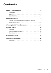
Contents About Your Computer 5 Front View 5 Back View 6 Specifications 6 Before You Begin 7 Turn Off Your Computer and Connected Devices 7 Safety Instructions 8 Working Inside Your Computer 9 System Setup 10 Overview 10 Entering System Setup 10 Boot Sequence 15 Flashing the BIOS 17 Contacting Alienware 18 Websites 18 Contents | 3
Contents About Your Computer 5 Front View 5 Back View 6 Specifications 6 Before You Begin 7 Turn Off Your Computer and Connected Devices 7 Safety Instructions 8 Working Inside Your Computer 9 System Setup 10 Overview 10 Entering System Setup 10 Boot Sequence 15 Flashing the BIOS 17 Contacting Alienware 18 Websites 18 Contents | 3

Owner's Manual
Page 5
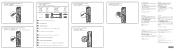
About Your Computer Front View 1 2 7 6 3 5 4 1 power button 3 optical drive 5 microphone port 7 USB 3.0 ports (2) 2 optical-drive eject button 4 rotatable AlienHead 6 headphone port NOTE: Your Alienware X51 R2 computer supports dual orientation. You can place your computer. The rotatable AlienHead allows you to change the direction of the AlienHead depending on the orientation of your computer vertically or horizontally. About Your Computer | 5
About Your Computer Front View 1 2 7 6 3 5 4 1 power button 3 optical drive 5 microphone port 7 USB 3.0 ports (2) 2 optical-drive eject button 4 rotatable AlienHead 6 headphone port NOTE: Your Alienware X51 R2 computer supports dual orientation. You can place your computer. The rotatable AlienHead allows you to change the direction of the AlienHead depending on the orientation of your computer vertically or horizontally. About Your Computer | 5
Owner's Manual
Page 6
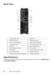
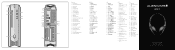
...2 3 4 17 16 5 15 6 14 7 8 13 12 9 11 10 1 optical S/PDIF port 3 USB 3.0 ports (2) 5 rear L/R surround port 7 microphone port 9 label tab 11 discrete graphics card 13 line-in port 15 security-cable slot 17 network port and network lights 2 HDMI port 4 USB 2.0 ports (2) 6 side L/R surround port 8 hard-drive activity light 10 power adapter port 12 line-out port 14 center/subwoofer LFE port 16 USB 3.0 ports (2) 18 coaxial S/PDIF port Specifications For detailed information regarding the configuration of your computer, see Specifications at dell.com/support. 6 | About Your Computer
...2 3 4 17 16 5 15 6 14 7 8 13 12 9 11 10 1 optical S/PDIF port 3 USB 3.0 ports (2) 5 rear L/R surround port 7 microphone port 9 label tab 11 discrete graphics card 13 line-in port 15 security-cable slot 17 network port and network lights 2 HDMI port 4 USB 2.0 ports (2) 6 side L/R surround port 8 hard-drive activity light 10 power adapter port 12 line-out port 14 center/subwoofer LFE port 16 USB 3.0 ports (2) 18 coaxial S/PDIF port Specifications For detailed information regarding the configuration of your computer, see Specifications at dell.com/support. 6 | About Your Computer
Owner's Manual
Page 7
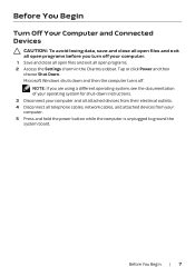
... all telephone cables, network cables, and attached devices from your computer and all attached devices from their electrical outlets. 4 Disconnect all open programs. 2 Access the Settings charm in the Charms sidebar. Before You Begin Turn Off Your Computer and Connected Devices CAUTION: To avoid losing data, save and close all open files and exit all open programs before you are using a different operating system, see...
... all telephone cables, network cables, and attached devices from your computer and all attached devices from their electrical outlets. 4 Disconnect all open programs. 2 Access the Settings charm in the Charms sidebar. Before You Begin Turn Off Your Computer and Connected Devices CAUTION: To avoid losing data, save and close all open files and exit all open programs before you are using a different operating system, see...
Owner's Manual
Page 8
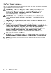
...work surface is authorized to remove the computer cover and access any connector pins. When disconnecting cables, keep them evenly aligned to help ensure your personal safety. NOTE: Ensure that the connectors and ports are correctly oriented and aligned. When connecting cables, ensure that you remove the security cable from the security-cable slot... a cable, pull on its connector or on its pull-tab, not on the cable itself. CAUTION: To disconnect a network cable, first unplug the cable from your computer and then unplug the cable from the network device. Safety Instructions Use the ...
...work surface is authorized to remove the computer cover and access any connector pins. When disconnecting cables, keep them evenly aligned to help ensure your personal safety. NOTE: Ensure that the connectors and ports are correctly oriented and aligned. When connecting cables, ensure that you remove the security cable from the security-cable slot... a cable, pull on its connector or on its pull-tab, not on the cable itself. CAUTION: To disconnect a network cable, first unplug the cable from your computer and then unplug the cable from the network device. Safety Instructions Use the ...
Owner's Manual
Page 9
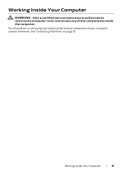
See "Contacting Alienware" on removing and replacing the internal component of the components inside the computer. Working Inside Your Computer | 9 For information on page 18. Working Inside Your Computer WARNING: Only a certified service technician is authorized to remove the computer cover and access any of your computer, contact Alienware.
See "Contacting Alienware" on removing and replacing the internal component of the components inside the computer. Working Inside Your Computer | 9 For information on page 18. Working Inside Your Computer WARNING: Only a certified service technician is authorized to remove the computer cover and access any of your computer, contact Alienware.
Owner's Manual
Page 10
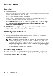
...; change the system configuration information • set or change a user-selectable option, such as user password, type of hard drive installed, enabling or disabling base devices, and so on CAUTION: Unless you see the Microsoft Windows desktop. Entering System Setup 1 Turn on (or restart) your computer work incorrectly. This prompt can make your computer. 2 During POST, when the Alienware logo is divided into three areas: the Setup Item, active Help Screen, and Key Functions. 10 | System Setup...
...; change the system configuration information • set or change a user-selectable option, such as user password, type of hard drive installed, enabling or disabling base devices, and so on CAUTION: Unless you see the Microsoft Windows desktop. Entering System Setup 1 Turn on (or restart) your computer work incorrectly. This prompt can make your computer. 2 During POST, when the Alienware logo is divided into three areas: the Setup Item, active Help Screen, and Key Functions. 10 | System Setup...
Owner's Manual
Page 11
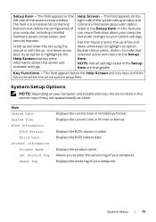
... your computer and installed devices, the items listed in this field you to your computer, including installed hardware, power conservation, and security features. Displays the asset tag of the system setup window. Scroll up -arrow and down-arrow keys to the Setup Item. As an option is a scrollable list containing features that option and available settings. Displays the BIOS version number. Displays the BIOS release date. System Setup | 11 Displays the current...
... your computer and installed devices, the items listed in this field you to your computer, including installed hardware, power conservation, and security features. Displays the asset tag of the system setup window. Scroll up -arrow and down-arrow keys to the Setup Item. As an option is a scrollable list containing features that option and available settings. Displays the BIOS version number. Displays the BIOS release date. System Setup | 11 Displays the current...
Owner's Manual
Page 12
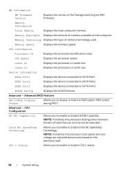
... the version of memory technology used. SATA Port3 Displays the device connected to enable or disable CPU C states. 12 | System Setup Advanced - Advanced - Memory Information Total Memory Displays the total computer memory. CPU Information Processor ID Displays the processor identification code. Cache L3 Displays the processor L3 cache size. CPU C States Allows you to enable or disable Intel (R) Speedstep Technology. Memory Technology Displays the type of the Management Engine (ME) Firmware. CPU Speed Displays the processor speed. CPU Configuration XD Bit...
... the version of memory technology used. SATA Port3 Displays the device connected to enable or disable CPU C states. 12 | System Setup Advanced - Advanced - Memory Information Total Memory Displays the total computer memory. CPU Information Processor ID Displays the processor identification code. Cache L3 Displays the processor L3 cache size. CPU C States Allows you to enable or disable Intel (R) Speedstep Technology. Memory Technology Displays the type of the Management Engine (ME) Firmware. CPU Speed Displays the processor speed. CPU Configuration XD Bit...
Owner's Manual
Page 13
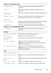
... integrated USB controller. Security Supervisor Password: Displays the Supervisor Password status. Wait For 'F1' If Error If enabled, the system HALT during boot to disable Boot Menu Security. Onboard LAN Controller Allows you to enable to set or change a user password. Set Supervisor Password Allows you to disable boot option for UEFI (Unified Extensible Firmware Interface) Network Devices. User Password: Displays the User Password status. Secure Boot Control Allows you to set or change a supervisor password. Power Management Setup AC Recovery Sets...
... integrated USB controller. Security Supervisor Password: Displays the Supervisor Password status. Wait For 'F1' If Error If enabled, the system HALT during boot to disable Boot Menu Security. Onboard LAN Controller Allows you to enable to set or change a user password. Set Supervisor Password Allows you to disable boot option for UEFI (Unified Extensible Firmware Interface) Network Devices. User Password: Displays the User Password status. Secure Boot Control Allows you to set or change a supervisor password. Power Management Setup AC Recovery Sets...
Owner's Manual
Page 14
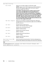
... be partitioned to Save Changes and Reset, Discard Changes and Reset, and Restore Defaults. 14 | System Setup NOTE: Legacy boot mode if selected, enables booting to the hard drives detected. CAUTION: Changing boot modes require that support Legacy BIOS. Set Boot Priority Boot Mode Allows you to enable or disable booting from USB mass storage devices such as hard drive, optical drive, USB flash drives, and so on. 1st Boot Displays the first boot device. UEFI boot mode if selected, enables UEFI drivers. Usb Boot Support Allows you to select Legacy or UEFI boot mode. Hard Disk...
... be partitioned to Save Changes and Reset, Discard Changes and Reset, and Restore Defaults. 14 | System Setup NOTE: Legacy boot mode if selected, enables booting to the hard drives detected. CAUTION: Changing boot modes require that support Legacy BIOS. Set Boot Priority Boot Mode Allows you to enable or disable booting from USB mass storage devices such as hard drive, optical drive, USB flash drives, and so on. 1st Boot Displays the first boot device. UEFI boot mode if selected, enables UEFI drivers. Usb Boot Support Allows you to select Legacy or UEFI boot mode. Hard Disk...
Owner's Manual
Page 15
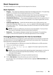
... Boot Options appears, listing all available boot devices. 4 On the Boot Options choose the device you want to boot from the floppy disk drive. The computer attempts to boot from . The BIOS detects the device and adds the USB flash option to a USB device, the device must be bootable. Boot Options • Floppy - Changing Boot Sequence for the Current Boot You can use this feature to change the boot sequence for example, to boot from the optical drive to run Dell Diagnostics from the Drivers and Utilities disc. Boot...
... Boot Options appears, listing all available boot devices. 4 On the Boot Options choose the device you want to boot from the floppy disk drive. The computer attempts to boot from . The BIOS detects the device and adds the USB flash option to a USB device, the device must be bootable. Boot Options • Floppy - Changing Boot Sequence for the Current Boot You can use this feature to change the boot sequence for example, to boot from the optical drive to run Dell Diagnostics from the Drivers and Utilities disc. Boot...
Owner's Manual
Page 16
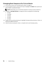
... current boot sequence in case you want to restore it. 3 Navigate to Set Boot Priority to change the devices assigned to the following: - 1st Boot - 2nd Boot - 3rd Boot - 4th Boot - 5th Boot 4 Double-click or use the arrow keys to highlight the Boot menu option and press to set the boot priority. 16 | System Setup Changing Boot Sequence for Future Boots 1 Enter system setup. See "Entering System Setup" on page 10. 2 Scroll using the mouse or use the arrow keys...
... current boot sequence in case you want to restore it. 3 Navigate to Set Boot Priority to change the devices assigned to the following: - 1st Boot - 2nd Boot - 3rd Boot - 4th Boot - 5th Boot 4 Double-click or use the arrow keys to highlight the Boot menu option and press to set the boot priority. 16 | System Setup Changing Boot Sequence for Future Boots 1 Enter system setup. See "Entering System Setup" on page 10. 2 Scroll using the mouse or use the arrow keys...
Owner's Manual
Page 17
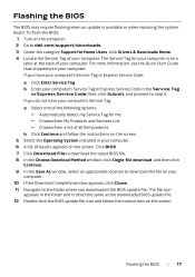
... and Services List - Automatically detect my Service Tag for Home Users, click Drivers & Downloads Home. 4 Locate the Service Tag of your computer. 6 A list of all Dell products b Click Continue and follow the instructions on the screen. 5 Select the Operating System installed in the folder and is available or when replacing the system board. Flashing the BIOS The BIOS may require flashing when an update is titled the same as the downloaded BIOS update file...
... and Services List - Automatically detect my Service Tag for Home Users, click Drivers & Downloads Home. 4 Locate the Service Tag of your computer. 6 A list of all Dell products b Click Continue and follow the instructions on the screen. 5 Select the Operating System installed in the folder and is available or when replacing the system board. Flashing the BIOS The BIOS may require flashing when an update is titled the same as the downloaded BIOS update file...
Owner's Manual
Page 18
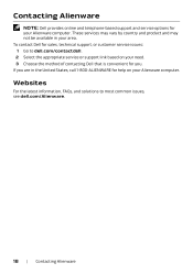
... your need. 3 Choose the method of contacting Dell that is convenient for help on your Alienware computer. If you . These services may vary by country and product and may not be available in the United States, call 1-800-ALIENWARE for you are in your Alienware computer. Contacting Alienware NOTE: Dell provides online and telephone-based support and service options for sales, technical support...
... your need. 3 Choose the method of contacting Dell that is convenient for help on your Alienware computer. If you . These services may vary by country and product and may not be available in the United States, call 1-800-ALIENWARE for you are in your Alienware computer. Contacting Alienware NOTE: Dell provides online and telephone-based support and service options for sales, technical support...
Quick Start Guide
Page 1
.... Discrete graphics card 21 21 18 표시등 22. Center/Subwoofer LFE port 23 LFE 插孔 23 LFE 連 21 21 24. Security-cable slot 24 接埠 20 22 24 21 22 23 LFE 포트 24 20 23 LFE ポート X51 24 Quick Start Guide Optical drive 2 3 2 3. 光碟機 2 2 4. Microphone port 5 5 4. USB 3.0 ポート (2) 7. USB 3.0 ports (2) 12. USB...
.... Discrete graphics card 21 21 18 표시등 22. Center/Subwoofer LFE port 23 LFE 插孔 23 LFE 連 21 21 24. Security-cable slot 24 接埠 20 22 24 21 22 23 LFE 포트 24 20 23 LFE ポート X51 24 Quick Start Guide Optical drive 2 3 2 3. 光碟機 2 2 4. Microphone port 5 5 4. USB 3.0 ポート (2) 7. USB 3.0 ports (2) 12. USB...
Quick Start Guide
Page 2
... 11950 México, D.F. 1 Connect the keyboard and mouse 2 Connect the network cable (optional) 3 Connect the display Connection Type Computer Cable and Adapter DVI DVI HDMI HDMI Display NOTE: Connect the display to the discrete graphics card NOTE: Display cables and adapters may not ship with your computer 4 Connect the power cable 5 Press the power button Locate the Service Tag More Information To contact Dell for sales, tech support, or customer service issues, go to change without notice. © 2013 Dell Inc. For the...
... 11950 México, D.F. 1 Connect the keyboard and mouse 2 Connect the network cable (optional) 3 Connect the display Connection Type Computer Cable and Adapter DVI DVI HDMI HDMI Display NOTE: Connect the display to the discrete graphics card NOTE: Display cables and adapters may not ship with your computer 4 Connect the power cable 5 Press the power button Locate the Service Tag More Information To contact Dell for sales, tech support, or customer service issues, go to change without notice. © 2013 Dell Inc. For the...


