Mobile Manual
Page 11
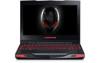
... the laptop may see the documentation for technical information or general use as you explore your new laptop's capabilities. The media included with your Alienware® laptop is designed to provide answers to many of the questions that may arise as needed to complete certain tasks. When placing your ...location or in any kind on a surface that is both level and stable. • The power and other external storage drives can be easily accessed. 11 Placing Your Laptop WARNING: Do not place the laptop near or over a radiator or heating vent. If your laptop is placed in a cabinet, ensure...
... the laptop may see the documentation for technical information or general use as you explore your new laptop's capabilities. The media included with your Alienware® laptop is designed to provide answers to many of the questions that may arise as needed to complete certain tasks. When placing your ...location or in any kind on a surface that is both level and stable. • The power and other external storage drives can be easily accessed. 11 Placing Your Laptop WARNING: Do not place the laptop near or over a radiator or heating vent. If your laptop is placed in a cabinet, ensure...
Mobile Manual
Page 92
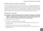
CHAPTER 7: SPECIFICATIONS Computer Model Alienware M11x-R2 Dimensions Height (front and back) Width Depth Weight with 8-cell battery (starting at) 32.7 mm (1.29 inches) 285.7 mm (11.25 inches) 233.3 mm (9.19 inches) 2.0 kg (4.4 lbs) NOTE: The weight of your laptop will vary depending on the configuration ordered and the manufacturing variability. 92
CHAPTER 7: SPECIFICATIONS Computer Model Alienware M11x-R2 Dimensions Height (front and back) Width Depth Weight with 8-cell battery (starting at) 32.7 mm (1.29 inches) 285.7 mm (11.25 inches) 233.3 mm (9.19 inches) 2.0 kg (4.4 lbs) NOTE: The weight of your laptop will vary depending on the configuration ordered and the manufacturing variability. 92

Mobile Manual
Page 98
CHAPTER 7: SPECIFICATIONS Display Type Maximum resolution Dimensions Height Width Diagonal Refresh rate Operating angle Pixel pitch Controls 11.6 inch HD TrueLife, WLED 1366 x 768 144 mm (5.67 inches) 256.12 mm (10.08 inches) 293.83 mm (11.57 inches) 60 Hz 0° (closed) to 140° 0.2550 mm brightness can be controlled through keyboard shortcuts 98
CHAPTER 7: SPECIFICATIONS Display Type Maximum resolution Dimensions Height Width Diagonal Refresh rate Operating angle Pixel pitch Controls 11.6 inch HD TrueLife, WLED 1366 x 768 144 mm (5.67 inches) 256.12 mm (10.08 inches) 293.83 mm (11.57 inches) 60 Hz 0° (closed) to 140° 0.2550 mm brightness can be controlled through keyboard shortcuts 98

Mobile Manual
Page 100
CHAPTER 7: SPECIFICATIONS Battery 8-cell "smart" lithium ion (63 Whr) Height 11.2 mm (0.44 inches) Width 173 mm (6.81 inches) Depth 109.4 mm (4.31 inches) Weight 0.43 kg (0.94 lb) Voltage Operating time Life span (approximate) Temperature range Operating Storage Coin-cell battery 14.8 V battery operating time varies depending on operating conditions and can be significantly reduced under certain power-intensive conditions. 300 discharge/charge cycles 0° to 50°C (32° to 122°F) -20° to 60°C (-4° to 140°F) CR-2032 100
CHAPTER 7: SPECIFICATIONS Battery 8-cell "smart" lithium ion (63 Whr) Height 11.2 mm (0.44 inches) Width 173 mm (6.81 inches) Depth 109.4 mm (4.31 inches) Weight 0.43 kg (0.94 lb) Voltage Operating time Life span (approximate) Temperature range Operating Storage Coin-cell battery 14.8 V battery operating time varies depending on operating conditions and can be significantly reduced under certain power-intensive conditions. 300 discharge/charge cycles 0° to 50°C (32° to 122°F) -20° to 60°C (-4° to 140°F) CR-2032 100

Mobile Manual
Page 111
... - Flat 11° Col. APPENDIX Information for NOM, or Official Mexican Standard (Only for Mexico) The following information is provided in the device(s) described in this document in accordance with your computer. Lomas Altas 11950 México, D.F. For additional safety best practices information, see the Regulatory Compliance Homepage at www.dell.com...
... - Flat 11° Col. APPENDIX Information for NOM, or Official Mexican Standard (Only for Mexico) The following information is provided in the device(s) described in this document in accordance with your computer. Lomas Altas 11950 México, D.F. For additional safety best practices information, see the Regulatory Compliance Homepage at www.dell.com...
Service Manual
Page 14
Back to Contents Page Display Assembly Alienware® M11x R2 Service Manual Removing the Display Assembly Replacing the Display Assembly WARNING: Before working inside your computer, read the safety information that is not authorized by Dell™ is not covered by periodically touching an unpainted...from the connector on the computer base. 1 Mini-Card antenna cables 8. Remove the battery pack (see Removing the Keyboard). 11. For additional safety best practices information, see Removing the Palm Rest Assembly). 12. CAUTION: To avoid electrostatic discharge, ground ...
Back to Contents Page Display Assembly Alienware® M11x R2 Service Manual Removing the Display Assembly Replacing the Display Assembly WARNING: Before working inside your computer, read the safety information that is not authorized by Dell™ is not covered by periodically touching an unpainted...from the connector on the computer base. 1 Mini-Card antenna cables 8. Remove the battery pack (see Removing the Keyboard). 11. For additional safety best practices information, see Removing the Palm Rest Assembly). 12. CAUTION: To avoid electrostatic discharge, ground ...

Service Manual
Page 15
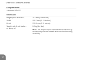
... the four screws that secure the display assembly to the computer base. 1 screws (4) 2 display cable connector 14. Replace the keyboard (see Replacing the Memory Module(s)). 11. Replace the memory module(s) (see Replacing the Keyboard). 9. Lift the display assembly off the computer. Follow the instructions from step 6 to the Mini-Card(s). 7. Replace...
... the four screws that secure the display assembly to the computer base. 1 screws (4) 2 display cable connector 14. Replace the keyboard (see Replacing the Memory Module(s)). 11. Replace the memory module(s) (see Replacing the Keyboard). 9. Lift the display assembly off the computer. Follow the instructions from step 6 to the Mini-Card(s). 7. Replace...

Service Manual
Page 20
CAUTION: Before turning on the computer, replace all screws and ensure that no stray screws remain inside the computer. Install the operating system for your computer, as needed . 12. Back to the computer. 11. Install the drivers and utilities for your computer, as needed . Failure to do so may result in damage to Contents Page
CAUTION: Before turning on the computer, replace all screws and ensure that no stray screws remain inside the computer. Install the operating system for your computer, as needed . 12. Back to the computer. 11. Install the drivers and utilities for your computer, as needed . Failure to do so may result in damage to Contents Page
Service Manual
Page 23
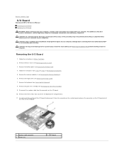
...: To help prevent damage to Contents Page I/O Board Alienware® M11x R2 Service Manual Removing the I/O Board Replacing the I /O... board. 10. Remove the base cover (see Removing the Hinge Cover). 7. Follow the instructions from the connector on the computer. 1 speaker cable connector 3 screws (3) 2 I /O board to servicing that secure the I /O Board 1. Disconnect the speaker cable from step 4 to the computer base. 11... the three screws that is not authorized by Dell™ is not covered by periodically touching an...
...: To help prevent damage to Contents Page I/O Board Alienware® M11x R2 Service Manual Removing the I/O Board Replacing the I /O... board. 10. Remove the base cover (see Removing the Hinge Cover). 7. Follow the instructions from the connector on the computer. 1 speaker cable connector 3 screws (3) 2 I /O board to servicing that secure the I /O Board 1. Disconnect the speaker cable from step 4 to the computer base. 11... the three screws that is not authorized by Dell™ is not covered by periodically touching an...
Service Manual
Page 24
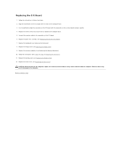
... Module(s)). 10. Failure to the computer. Follow the instructions from step 6 to step 8 in damage to do so may result in Replacing the Hard Drive. 11. Replace the palm rest assembly (see Replacing the Battery Pack). 12. Replace the battery pack (see Replacing the Palm Rest Assembly). 7. Replace the three screws...
... Module(s)). 10. Failure to the computer. Follow the instructions from step 6 to step 8 in damage to do so may result in Replacing the Hard Drive. 11. Replace the palm rest assembly (see Replacing the Battery Pack). 12. Replace the battery pack (see Replacing the Palm Rest Assembly). 7. Replace the three screws...

Service Manual
Page 26
... 13. Gently press around the edges of the slots on the palm rest assembly and lower the keyboard into the slots on the palm rest. 11. Carefully turn the computer over and place it on the palm rest assembly. 5. Follow the instructions in Before You Begin. 2. Replace the memory module(s) (see...
... 13. Gently press around the edges of the slots on the palm rest assembly and lower the keyboard into the slots on the palm rest. 11. Carefully turn the computer over and place it on the palm rest assembly. 5. Follow the instructions in Before You Begin. 2. Replace the memory module(s) (see...

Service Manual
Page 27
Replace the base cover (see Replacing the Battery Pack). 12. Failure to do so may result in Replacing the Hard Drive. 11. Replace the battery pack (see Replacing the Base Cover). CAUTION: Before turning on the computer, replace all screws and ensure that no stray screws remain inside the computer. Back to the computer. 10. Follow the instructions from step 6 to step 8 in damage to Contents Page
Replace the base cover (see Replacing the Battery Pack). 12. Failure to do so may result in Replacing the Hard Drive. 11. Replace the battery pack (see Replacing the Base Cover). CAUTION: Before turning on the computer, replace all screws and ensure that no stray screws remain inside the computer. Back to the computer. 10. Follow the instructions from step 6 to step 8 in damage to Contents Page
Service Manual
Page 28
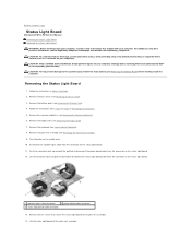
...strap or by your warranty. Lift the status light board off the palm rest assembly. Back to Contents Page Status Light Board Alienware® M11x R2 Service Manual Removing the Status Light Board Replacing the Status Light Board WARNING: Before working inside your computer, read the safety ...Only a certified service technician should perform repairs on the status light board. 11. CAUTION: To help prevent damage to disconnect the status light board cable from step 4 to servicing that is not authorized by Dell™ is not covered by periodically touching an unpainted metal surface (such...
...strap or by your warranty. Lift the status light board off the palm rest assembly. Back to Contents Page Status Light Board Alienware® M11x R2 Service Manual Removing the Status Light Board Replacing the Status Light Board WARNING: Before working inside your computer, read the safety ...Only a certified service technician should perform repairs on the status light board. 11. CAUTION: To help prevent damage to disconnect the status light board cable from step 4 to servicing that is not authorized by Dell™ is not covered by periodically touching an unpainted metal surface (such...

Service Manual
Page 29
Follow the instructions in damage to secure the cable. 6. Connect the speaker lights cable to step 8 in Replacing the Hard Drive. 11. Insert the status light board cable into the connector on the status light board and press the connector latch into the connector on the status ...
Follow the instructions in damage to secure the cable. 6. Connect the speaker lights cable to step 8 in Replacing the Hard Drive. 11. Insert the status light board cable into the connector on the status light board and press the connector latch into the connector on the status ...
Service Manual
Page 34
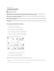
...Damage due to servicing that secure the palm rest to the computer base. 7. CAUTION: Pull the pull-tabs on the system board. 11. CAUTION: To avoid electrostatic discharge, ground yourself by using a wrist grounding strap or by your warranty. CAUTION: To help prevent damage ... Regulatory Compliance Homepage at www.dell.com/regulatory_compliance. Remove the three screws that shipped with your computer, read the safety information that secure the palm rest assembly to the computer base. Back to Contents Page Palm Rest Assembly Alienware® M11x R2 Service Manual Removing the Palm...
...Damage due to servicing that secure the palm rest to the computer base. 7. CAUTION: Pull the pull-tabs on the system board. 11. CAUTION: To avoid electrostatic discharge, ground yourself by using a wrist grounding strap or by your warranty. CAUTION: To help prevent damage ... Regulatory Compliance Homepage at www.dell.com/regulatory_compliance. Remove the three screws that shipped with your computer, read the safety information that secure the palm rest assembly to the computer base. Back to Contents Page Palm Rest Assembly Alienware® M11x R2 Service Manual Removing the Palm...

Service Manual
Page 36
Follow the instructions from step 6 to step 8 in damage to do so may result in Replacing the Hard Drive. 11. Replace the keyboard (see Replacing the Memory Module(s)). 12. Replace the memory module(s) (see Replacing the Keyboard). 7. 6. Replace the nine screws that no stray screws ...
Follow the instructions from step 6 to step 8 in damage to do so may result in Replacing the Hard Drive. 11. Replace the keyboard (see Replacing the Memory Module(s)). 12. Replace the memory module(s) (see Replacing the Keyboard). 7. 6. Replace the nine screws that no stray screws ...
Service Manual
Page 37
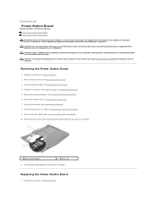
... light board (see Removing the Hinge Cover). 7. Replacing the Power Button Board 1. Back to Contents Page Power Button Board Alienware® M11x R2 Service Manual Removing the Power Button Board Replacing the Power Button Board WARNING: Before working inside your computer, read the safety ...Follow the instructions from step 4 to the palm rest assembly. 1 power button board 2 screws (2) 11. Remove the keyboard (see the Regulatory Compliance Homepage at www.dell.com/regulatory_compliance. Lift the power button board off the palm rest assembly. CAUTION: To help prevent damage ...
... light board (see Removing the Hinge Cover). 7. Replacing the Power Button Board 1. Back to Contents Page Power Button Board Alienware® M11x R2 Service Manual Removing the Power Button Board Replacing the Power Button Board WARNING: Before working inside your computer, read the safety ...Follow the instructions from step 4 to the palm rest assembly. 1 power button board 2 screws (2) 11. Remove the keyboard (see the Regulatory Compliance Homepage at www.dell.com/regulatory_compliance. Lift the power button board off the palm rest assembly. CAUTION: To help prevent damage ...
Service Manual
Page 40
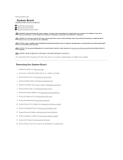
Damage due to servicing that is not authorized by Dell™ is also visible on a barcode label at www.dell.com/regulatory_compliance. Removing the System Board 1. Remove the Mini-Card(s) (.... Remove the memory module(s) (see Removing the Base Cover). 4. Back to Contents Page System Board Alienware® M11x R2 Service Manual Removing the System Board Replacing the System Board Entering the Service Tag in the BIOS WARNING...Remove the display assembly (see Removing the Palm Rest Assembly). 11. Remove the I/O board (see the Regulatory Compliance Homepage at the bottom of the computer.
Damage due to servicing that is not authorized by Dell™ is also visible on a barcode label at www.dell.com/regulatory_compliance. Removing the System Board 1. Remove the Mini-Card(s) (.... Remove the memory module(s) (see Removing the Base Cover). 4. Back to Contents Page System Board Alienware® M11x R2 Service Manual Removing the System Board Replacing the System Board Entering the Service Tag in the BIOS WARNING...Remove the display assembly (see Removing the Palm Rest Assembly). 11. Remove the I/O board (see the Regulatory Compliance Homepage at the bottom of the computer.
Service Manual
Page 41
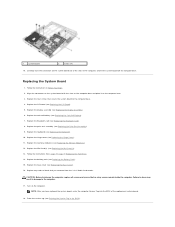
... system board off the computer base. Replace the hinge cover (see Replacing the Mini-Card(s)). 13. Replace the Mini-Card(s) (see Replacing the Hinge Cover). 11. NOTE: After you removed from step 6 to the computer. 17. Replace the coin-cell battery (see Replacing the Battery Pack). 15. Replace the battery pack...
... system board off the computer base. Replace the hinge cover (see Replacing the Mini-Card(s)). 13. Replace the Mini-Card(s) (see Replacing the Hinge Cover). 11. NOTE: After you removed from step 6 to the computer. 17. Replace the coin-cell battery (see Replacing the Battery Pack). 15. Replace the battery pack...


