Mobile Manual
Page 4
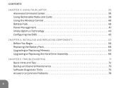
CONTENTS CHAPTER 3: USING YOUR LAPTOP 35 Alienware Command Center 36 Using Removable Media and Cards 39 Using the Wireless Control 40 Battery Pack 40 Power Management 41 nVidia Optimus Technology 43 Configuring the BIOS 45 CHAPTER 4: INSTALLING AND REPLACING COMPONENTS 55 Before You Begin 56 Replacing the Battery Pack 60 Upgrading or Replacing Memory 63 Upgrading or Replacing the Hard Drive Assembly 66 CHAPTER 5: TROUBLESHOOTING 71 Basic Hints and Tips 72 Backup and General Maintenance 73 Software Diagnostic Tools 75 Answers to Common Problems 78 4
CONTENTS CHAPTER 3: USING YOUR LAPTOP 35 Alienware Command Center 36 Using Removable Media and Cards 39 Using the Wireless Control 40 Battery Pack 40 Power Management 41 nVidia Optimus Technology 43 Configuring the BIOS 45 CHAPTER 4: INSTALLING AND REPLACING COMPONENTS 55 Before You Begin 56 Replacing the Battery Pack 60 Upgrading or Replacing Memory 63 Upgrading or Replacing the Hard Drive Assembly 66 CHAPTER 5: TROUBLESHOOTING 71 Basic Hints and Tips 72 Backup and General Maintenance 73 Software Diagnostic Tools 75 Answers to Common Problems 78 4
Mobile Manual
Page 64
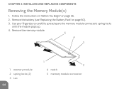
Remove the memory module. 5 4 3 1 memory module 2 spring locks (2) 3 tab 64 1 2 4 notch 5 memory module connector CHAPTER 4: INSTALLING AND REPLACING COMPONENTS Removing the Memory Module(s) 1. Remove the battery (see "Replacing the Battery Pack" on page 56. 2. Follow the instructions in "Before You Begin" on page 60). 3. Use your fingertips to carefully spread apart the memory module connector's spring-locks until the module pops up. 4.
Remove the memory module. 5 4 3 1 memory module 2 spring locks (2) 3 tab 64 1 2 4 notch 5 memory module connector CHAPTER 4: INSTALLING AND REPLACING COMPONENTS Removing the Memory Module(s) 1. Remove the battery (see "Replacing the Battery Pack" on page 56. 2. Follow the instructions in "Before You Begin" on page 60). 3. Use your fingertips to carefully spread apart the memory module connector's spring-locks until the module pops up. 4.
Service Manual
Page 1
...CAUTION: A CAUTION indicates potential damage to change without the written permission of your computer. Alienware® M11x R2 Service Manual Before You Begin Base Cover Battery Pack Hard Drive Memory Module(s) Wireless Mini-Card(s) Hinge Cover Keyboard Palm Rest Assembly Status Light Board Power Button Board Internal Card With Bluetooth® Wireless Technology Coin-Cell Battery Display Assembly I/O Board System Board Speakers System Setup Flashing the BIOS Notes, Cautions, and Warnings NOTE: A NOTE indicates important information that helps you make better use of Dell Inc.
...CAUTION: A CAUTION indicates potential damage to change without the written permission of your computer. Alienware® M11x R2 Service Manual Before You Begin Base Cover Battery Pack Hard Drive Memory Module(s) Wireless Mini-Card(s) Hinge Cover Keyboard Palm Rest Assembly Status Light Board Power Button Board Internal Card With Bluetooth® Wireless Technology Coin-Cell Battery Display Assembly I/O Board System Board Speakers System Setup Flashing the BIOS Notes, Cautions, and Warnings NOTE: A NOTE indicates important information that helps you make better use of Dell Inc.
Service Manual
Page 6
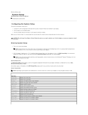
.... Displays the EC firmware version. Displays the speed of the BIOS Setup Utility window and lists keys and their functions within the active field. Entering System Setup 1. Displays the Intel® ME firmware version. Displays the ID of your computer. Displays the processor cache size. Back to Contents Page System Setup Alienware® M11x R2 Service Manual Configuring the System Setup Configuring the System Setup The System Setup options allow you to: l Change the system configuration information after you add, change or remove...
.... Displays the EC firmware version. Displays the speed of the BIOS Setup Utility window and lists keys and their functions within the active field. Entering System Setup 1. Displays the Intel® ME firmware version. Displays the ID of your computer. Displays the processor cache size. Back to Contents Page System Setup Alienware® M11x R2 Service Manual Configuring the System Setup Configuring the System Setup The System Setup options allow you to: l Change the system configuration information after you add, change or remove...
Service Manual
Page 7
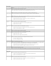
... internal Bluetooth device is disabled and is enabled. Wireless Network Allows you to enable or disable the internal SD card reader. l Enabled: The internal wireless device is not visible to choose if the computer should display warning messages when you use a power adapter that has too little capacity for ATA mode. Allows you to configure the operating mode of USB device (floppy, hard drive, or memory key) when this feature may not wake the computer. USB Emulation Allows you to enable or disable battery charging. l Enabled...
... internal Bluetooth device is disabled and is enabled. Wireless Network Allows you to enable or disable the internal SD card reader. l Enabled: The internal wireless device is not visible to choose if the computer should display warning messages when you use a power adapter that has too little capacity for ATA mode. Allows you to configure the operating mode of USB device (floppy, hard drive, or memory key) when this feature may not wake the computer. USB Emulation Allows you to enable or disable battery charging. l Enabled...
Service Manual
Page 10
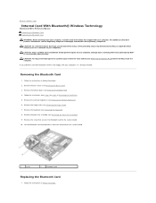
....dell.com/regulatory_compliance. Lift the Bluetooth card to disconnect it is not covered by Dell™ is already installed. For additional safety best practices information, see Removing the Battery Pack). 4. Remove the memory module(s) (see Removing the Keyboard). 8. Follow the instructions in Before You Begin Remove the keyboard (see Removing the Memory Module(s)). 6. Back to Contents Page Internal Card With Bluetooth® Wireless Technology Alienware® M11x R2 Service Manual Removing the Bluetooth Card Replacing the Bluetooth Card WARNING: Before working...
....dell.com/regulatory_compliance. Lift the Bluetooth card to disconnect it is not covered by Dell™ is already installed. For additional safety best practices information, see Removing the Battery Pack). 4. Remove the memory module(s) (see Removing the Keyboard). 8. Follow the instructions in Before You Begin Remove the keyboard (see Removing the Memory Module(s)). 6. Back to Contents Page Internal Card With Bluetooth® Wireless Technology Alienware® M11x R2 Service Manual Removing the Bluetooth Card Replacing the Bluetooth Card WARNING: Before working...

Service Manual
Page 12
... coin-cell battery from the connector on your warranty. Back to Contents Page Coin-Cell Battery Alienware® M11x R2 Service Manual Removing the Coin-Cell Battery Replacing the Coin-Cell Battery WARNING: Before working inside your computer). CAUTION: To avoid electrostatic discharge, ground yourself by using a wrist grounding strap or by your computer. CAUTION: To help prevent damage to step 6 in Removing the Hard Drive. 5.
... coin-cell battery from the connector on your warranty. Back to Contents Page Coin-Cell Battery Alienware® M11x R2 Service Manual Removing the Coin-Cell Battery Replacing the Coin-Cell Battery WARNING: Before working inside your computer). CAUTION: To avoid electrostatic discharge, ground yourself by using a wrist grounding strap or by your computer. CAUTION: To help prevent damage to step 6 in Removing the Hard Drive. 5.
Service Manual
Page 14
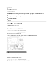
... the system board, remove the main battery (see Removing the Hinge Cover). 10. CAUTION: To help prevent damage to disconnect the display cable from step 4 to servicing that shipped with your warranty. Back to Contents Page Display Assembly Alienware® M11x R2 Service Manual Removing the Display Assembly Replacing the Display Assembly WARNING: Before working inside your computer, read the safety information that is not authorized by Dell™ is...
... the system board, remove the main battery (see Removing the Hinge Cover). 10. CAUTION: To help prevent damage to disconnect the display cable from step 4 to servicing that shipped with your warranty. Back to Contents Page Display Assembly Alienware® M11x R2 Service Manual Removing the Display Assembly Replacing the Display Assembly WARNING: Before working inside your computer, read the safety information that is not authorized by Dell™ is...
Service Manual
Page 18
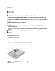
....dell.com/regulatory_compliance. Do not remove the hard drive while the computer is hot, do not touch the metal housing of cable, press in Before You Begin. 2. Remove the base cover (see Turning Off Your Computer) before working inside the computer. Also, before you are extremely fragile. Back to Contents Page Hard Drive Alienware® M11x R2 Service Manual Removing the Hard Drive Replacing the Hard Drive WARNING: If you need to install an operating system, drivers, and utilities...
....dell.com/regulatory_compliance. Do not remove the hard drive while the computer is hot, do not touch the metal housing of cable, press in Before You Begin. 2. Remove the base cover (see Turning Off Your Computer) before working inside the computer. Also, before you are extremely fragile. Back to Contents Page Hard Drive Alienware® M11x R2 Service Manual Removing the Hard Drive Replacing the Hard Drive WARNING: If you need to install an operating system, drivers, and utilities...
Service Manual
Page 19
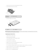
... hard drive. 8. Replacing the Hard Drive 1. Remove the new drive from the hard drive. 1 screws (4) 3 hard drive 2 hard-drive bracket 9. Lift the hard-drive bracket away from its packaging. Disconnect the interposer from the hard drive. 1 interposer 2 hard drive CAUTION: When the hard drive is not in the computer, store it in protective antistatic packaging (see "Protecting Against Electrostatic Discharge" in the computer base. 7. Connect the interposer to the hard drive. 6. Replace the base cover (see Replacing the Battery...
... hard drive. 8. Replacing the Hard Drive 1. Remove the new drive from the hard drive. 1 screws (4) 3 hard drive 2 hard-drive bracket 9. Lift the hard-drive bracket away from its packaging. Disconnect the interposer from the hard drive. 1 interposer 2 hard drive CAUTION: When the hard drive is not in the computer, store it in protective antistatic packaging (see "Protecting Against Electrostatic Discharge" in the computer base. 7. Connect the interposer to the hard drive. 6. Replace the base cover (see Replacing the Battery...
Service Manual
Page 21
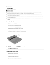
... a certified service technician should perform repairs on your computer. Remove the battery pack (see the Regulatory Compliance Homepage at www.dell.com/regulatory_compliance. CAUTION: To help prevent damage to the system board, remove the main battery (see Removing the Battery Pack) before working inside the computer. Removing the Hinge Cover 1. Back to Contents Page Hinge Cover Alienware® M11x R2 Service Manual Removing the Hinge Cover Replacing the Hinge Cover WARNING: Before working inside...
... a certified service technician should perform repairs on your computer. Remove the battery pack (see the Regulatory Compliance Homepage at www.dell.com/regulatory_compliance. CAUTION: To help prevent damage to the system board, remove the main battery (see Removing the Battery Pack) before working inside the computer. Removing the Hinge Cover 1. Back to Contents Page Hinge Cover Alienware® M11x R2 Service Manual Removing the Hinge Cover Replacing the Hinge Cover WARNING: Before working inside...
Service Manual
Page 23
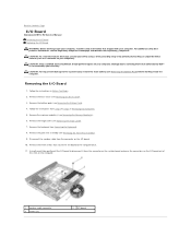
... the system board, remove the main battery (see the Regulatory Compliance Homepage at www.dell.com/regulatory_compliance. Follow the instructions in Removing the Hard Drive. 5. Remove the battery pack (see Removing the Palm Rest Assembly). 9. CAUTION: To avoid electrostatic discharge, ground yourself by using a wrist grounding strap or by your warranty. Back to Contents Page I/O Board Alienware® M11x R2 Service Manual Removing the I/O Board Replacing the I/O Board WARNING: Before working inside your...
... the system board, remove the main battery (see the Regulatory Compliance Homepage at www.dell.com/regulatory_compliance. Follow the instructions in Removing the Hard Drive. 5. Remove the battery pack (see Removing the Palm Rest Assembly). 9. CAUTION: To avoid electrostatic discharge, ground yourself by using a wrist grounding strap or by your warranty. Back to Contents Page I/O Board Alienware® M11x R2 Service Manual Removing the I/O Board Replacing the I/O Board WARNING: Before working inside your...
Service Manual
Page 25
... removing and handling the keyboard. CAUTION: Only a certified service technician should perform repairs on the keyboard are fragile, easily dislodged, and time-consuming to replace. Remove the base cover (see Removing the Battery Pack). 4. Follow the instructions from step 4 to step 6 in scratching the display panel. 7. Remove the battery pack (see Removing the Base Cover). 3. Back to Contents Page Keyboard Alienware® M11x R2 Service Manual Removing the Keyboard Replacing the Keyboard WARNING: Before working inside your computer). Remove...
... removing and handling the keyboard. CAUTION: Only a certified service technician should perform repairs on the keyboard are fragile, easily dislodged, and time-consuming to replace. Remove the base cover (see Removing the Battery Pack). 4. Follow the instructions from step 4 to step 6 in scratching the display panel. 7. Remove the battery pack (see Removing the Base Cover). 3. Back to Contents Page Keyboard Alienware® M11x R2 Service Manual Removing the Keyboard Replacing the Keyboard WARNING: Before working inside your computer). Remove...
Service Manual
Page 28
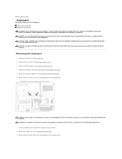
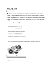
Back to Contents Page Status Light Board Alienware® M11x R2 Service Manual Removing the Status Light Board Replacing the Status Light Board WARNING: Before working inside your computer, read the safety information that shipped with your computer. CAUTION: To help prevent damage to disconnect the status light board cable from the connector on your computer. Remove the battery pack (see Removing the Memory Module(s)). 6. Remove the memory module(s) (see Removing the Battery Pack). 4. Turn the palm rest assembly...
Back to Contents Page Status Light Board Alienware® M11x R2 Service Manual Removing the Status Light Board Replacing the Status Light Board WARNING: Before working inside your computer, read the safety information that shipped with your computer. CAUTION: To help prevent damage to disconnect the status light board cable from the connector on your computer. Remove the battery pack (see Removing the Memory Module(s)). 6. Remove the memory module(s) (see Removing the Battery Pack). 4. Turn the palm rest assembly...
Service Manual
Page 30
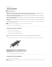
... connector before working inside the computer. Damage due to carefully spread apart the securing clips on the system board. Remove the memory module from Dell or Alienware are covered under your warranty. NOTE: Memory modules purchased from the memory-module connector. Follow the instructions in Before You Begin. 2. Your computer has two user-accessible SODIMM connectors. Use your fingertips to servicing that shipped with your computer. See "Specifications" in...
... connector before working inside the computer. Damage due to carefully spread apart the securing clips on the system board. Remove the memory module from Dell or Alienware are covered under your warranty. NOTE: Memory modules purchased from the memory-module connector. Follow the instructions in Before You Begin. 2. Your computer has two user-accessible SODIMM connectors. Use your fingertips to servicing that shipped with your computer. See "Specifications" in...
Service Manual
Page 31
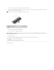
... confirm the amount of memory installed in the memory-module connector. 3. Back to the computer. 6. If you do so may not boot. 1 memory-module connector 3 notch 2 tab 4. Replace the battery pack (see Replacing the Base Cover). Align the notch in the memory module with the tab in the computer: Click Start ® Control Panel® System and Security® System. Turn on the computer, replace all screws and...
... confirm the amount of memory installed in the memory-module connector. 3. Back to the computer. 6. If you do so may not boot. 1 memory-module connector 3 notch 2 tab 4. Replace the battery pack (see Replacing the Base Cover). Align the notch in the memory module with the tab in the computer: Click Start ® Control Panel® System and Security® System. Turn on the computer, replace all screws and...
Service Manual
Page 33
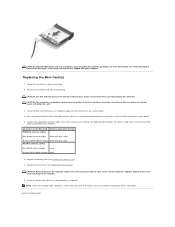
... other than Dell or Alienware, you are keyed to ensure correct insertion. Replace the battery pack (see Replacing the Base Cover). NOTE: If you must install the appropriate drivers and utilities. Back to the Mini-Card you may result in Before You Begin. 2. Remove the new Mini-Card from a source other end of the Mini-Card down into the slot on the system board and replace the screw...
... other than Dell or Alienware, you are keyed to ensure correct insertion. Replace the battery pack (see Replacing the Base Cover). NOTE: If you must install the appropriate drivers and utilities. Back to the Mini-Card you may result in Before You Begin. 2. Remove the new Mini-Card from a source other end of the Mini-Card down into the slot on the system board and replace the screw...
Service Manual
Page 34
...-tabs to disconnect the touch pad cable and status light board cable from step 4 to step 6 in Before You Begin. 2. CAUTION: To avoid electrostatic discharge, ground yourself by using a wrist grounding strap or by your computer). Follow the instructions in Removing the Hard Drive. 5. CAUTION: To help prevent damage to the system board, remove the main battery (see Removing the Battery Pack) before working inside the computer...
...-tabs to disconnect the touch pad cable and status light board cable from step 4 to step 6 in Before You Begin. 2. CAUTION: To avoid electrostatic discharge, ground yourself by using a wrist grounding strap or by your computer). Follow the instructions in Removing the Hard Drive. 5. CAUTION: To help prevent damage to the system board, remove the main battery (see Removing the Battery Pack) before working inside the computer...
Service Manual
Page 37
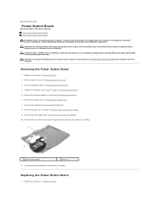
... Power Button Board Alienware® M11x R2 Service Manual Removing the Power Button Board Replacing the Power Button Board WARNING: Before working inside your computer, read the safety information that is not authorized by Dell™ is not covered by periodically touching an unpainted metal surface (such as a connector on your computer). Follow the instructions in Before You Begin. 2. Remove the base cover (see Removing the Battery Pack). 4. Remove the battery pack (see Removing the Base Cover). 3. Remove the memory module(s) (see Removing...
... Power Button Board Alienware® M11x R2 Service Manual Removing the Power Button Board Replacing the Power Button Board WARNING: Before working inside your computer, read the safety information that is not authorized by Dell™ is not covered by periodically touching an unpainted metal surface (such as a connector on your computer). Follow the instructions in Before You Begin. 2. Remove the base cover (see Removing the Battery Pack). 4. Remove the battery pack (see Removing the Base Cover). 3. Remove the memory module(s) (see Removing...
Service Manual
Page 40
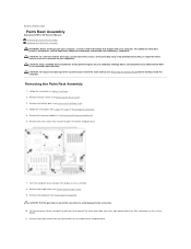
... the 3-in-1 Media Card reader. 3. Remove the memory module(s) (see Removing the Hinge Cover). 9. Remove the hinge cover (see Removing the Memory Module(s)). 8. Remove the keyboard (see Removing the Palm Rest Assembly). 11. Remove the palm rest assembly (see Removing the Keyboard). 10. Remove the coin-cell battery (see Removing the Display Assembly). 14. CAUTION: Handle components by your computer. Follow the instructions in Removing the Hard Drive. 6. Remove the display assembly (see Removing the Coin-Cell Battery). 13. Remove the four...
... the 3-in-1 Media Card reader. 3. Remove the memory module(s) (see Removing the Hinge Cover). 9. Remove the hinge cover (see Removing the Memory Module(s)). 8. Remove the keyboard (see Removing the Palm Rest Assembly). 11. Remove the palm rest assembly (see Removing the Keyboard). 10. Remove the coin-cell battery (see Removing the Display Assembly). 14. CAUTION: Handle components by your computer. Follow the instructions in Removing the Hard Drive. 6. Remove the display assembly (see Removing the Coin-Cell Battery). 13. Remove the four...


