

Setup and Quick Reference Guide
Page 22
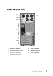
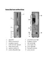
Vostro 420 Back View 1 2 7 6 5 3 4 1 power cord connector 3 security cable/padlock rings 5 back-panel connectors 7 voltage selector switch 2 power-supply vent 4 expansion card slots 6 power-supply light 22 About Your Computer
Vostro 420 Back View 1 2 7 6 5 3 4 1 power cord connector 3 security cable/padlock rings 5 back-panel connectors 7 voltage selector switch 2 power-supply vent 4 expansion card slots 6 power-supply light 22 About Your Computer
Setup and Quick Reference Guide
Page 25
Vostro 220 Back View 1 2 7 6 5 3 4 1 power cord connector 3 security cable/padlock rings 5 back-panel connectors 7 voltage selector switch 2 power-supply vent 4 expansion card slots 6 power-supply light About Your Computer 25
Vostro 220 Back View 1 2 7 6 5 3 4 1 power cord connector 3 security cable/padlock rings 5 back-panel connectors 7 voltage selector switch 2 power-supply vent 4 expansion card slots 6 power-supply light About Your Computer 25
Setup and Quick Reference Guide
Page 28
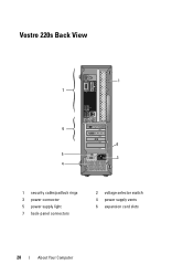
Vostro 220s Back View 1 7 6 2 5 3 4 1 security cable/padlock rings 3 power connector 5 power supply light 7 back-panel connectors 2 voltage selector switch 4 power supply vents 6 expansion card slots 28 About Your Computer
Vostro 220s Back View 1 7 6 2 5 3 4 1 security cable/padlock rings 3 power connector 5 power supply light 7 back-panel connectors 2 voltage selector switch 4 power supply vents 6 expansion card slots 28 About Your Computer
Setup and Quick Reference Guide
Page 32
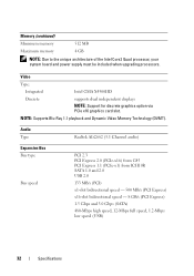
...-x1) from ICH10R SATA 1.0 and 2.0 USB 2.0 133 MB/s (PCI) x1-slot bidirectional speed - 500 MB/s (PCI Express) x16-slot bidirectional speed - 8 GB/s (PCI Express) 1.5 Gbps and 3.0 Gbps (SATA) 480-Mbps high speed, 12-Mbps full speed, 1.2-Mbps low speed (USB) 32 Specifications Video Type: Integrated ... Support for discrete graphics option via PCIe x16 graphics card slot. Memory (continued) Minimum memory 512 MB Maximum memory 4 GB NOTE: Due to the unique architecture of the Intel Core2 Quad processor, your system board and power supply must be included when upgrading processors.
...-x1) from ICH10R SATA 1.0 and 2.0 USB 2.0 133 MB/s (PCI) x1-slot bidirectional speed - 500 MB/s (PCI Express) x16-slot bidirectional speed - 8 GB/s (PCI Express) 1.5 Gbps and 3.0 Gbps (SATA) 480-Mbps high speed, 12-Mbps full speed, 1.2-Mbps low speed (USB) 32 Specifications Video Type: Integrated ... Support for discrete graphics option via PCIe x16 graphics card slot. Memory (continued) Minimum memory 512 MB Maximum memory 4 GB NOTE: Due to the unique architecture of the Intel Core2 Quad processor, your system board and power supply must be included when upgrading processors.

Setup and Quick Reference Guide
Page 36
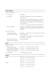
...Power 12V Power one 10-pin connector one 775-pin connector Vostro 420: four 240-pin connectors Vostro 220/220s: two 240-pin connectors one 4-pin connector one 24-pin connector Controls and Lights Front of computer: Link integrity light (on green light - Blinking amber indicates a power problem sensed by the power supply... yellow blinking light integrated network adapter) 36 Specifications The computer is in sleep state; Rear of computer: Power button push button Power light blue light - System is not detecting a physical connection to the SATA hard drive or CD/DVD. Solid...
...Power 12V Power one 10-pin connector one 775-pin connector Vostro 420: four 240-pin connectors Vostro 220/220s: two 240-pin connectors one 4-pin connector one 24-pin connector Controls and Lights Front of computer: Link integrity light (on green light - Blinking amber indicates a power problem sensed by the power supply... yellow blinking light integrated network adapter) 36 Specifications The computer is in sleep state; Rear of computer: Power button push button Power light blue light - System is not detecting a physical connection to the SATA hard drive or CD/DVD. Solid...
Setup and Quick Reference Guide
Page 37
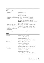
...: Heat dissipation is calculated by using the power supply wattage rating. Power DC power supply: Wattage Vostro 420: 350 W Vostro 220: 300 W Vostro 220s: 250 W Maximum heat dissipation for 350 W power supply, 1194 BTU/hr (MHD) for 300 W power supply, 1023 BTU/hr for important voltage setting information) Vostro 420: 115/230 VAC, 50/60 Hz, 8A/4A Vostro 220: 115/230 VAC, 50/60 Hz, 7A...
...: Heat dissipation is calculated by using the power supply wattage rating. Power DC power supply: Wattage Vostro 420: 350 W Vostro 220: 300 W Vostro 220s: 250 W Maximum heat dissipation for 350 W power supply, 1194 BTU/hr (MHD) for 300 W power supply, 1023 BTU/hr for important voltage setting information) Vostro 420: 115/230 VAC, 50/60 Hz, 8A/4A Vostro 220: 115/230 VAC, 50/60 Hz, 7A...
Setup and Features Information Tech Sheet
Page 2
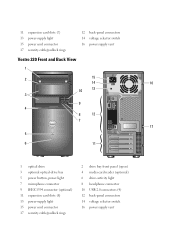
... back-panel connectors 14 voltage selector switch 16 power-supply vent Vostro 220 Front and Back View 1 2 15 14 16 10 13 3 9 4 8 12 7 17 5 6 11 1 optical drive 3 optional optical-drive bay 5 power button, power light 7 microphone connector 9 IEEE 1394 connector (optional) 11 expansion card slots (8) 13 power-supply light 15 power cord connector 17 security cable/padlock rings 2 drive...
... back-panel connectors 14 voltage selector switch 16 power-supply vent Vostro 220 Front and Back View 1 2 15 14 16 10 13 3 9 4 8 12 7 17 5 6 11 1 optical drive 3 optional optical-drive bay 5 power button, power light 7 microphone connector 9 IEEE 1394 connector (optional) 11 expansion card slots (8) 13 power-supply light 15 power cord connector 17 security cable/padlock rings 2 drive...
Setup and Features Information Tech Sheet
Page 3
Vostro 220s Front and Back View 7 13 1 12 2 3 4 5 6 1 optical drive 3 USB 2.0 connectors (2) 5 microphone connector 7 media card reader (optional) 9 voltage selector switch 11 expansion card slots (4) 13 security cable/padlock rings 11 10 14 9 8 2 power button, power light 4 headphone connector 6 drive-activity light 8 power supply vents 10 power supply light 12 back-panel connectors 14 power connector
Vostro 220s Front and Back View 7 13 1 12 2 3 4 5 6 1 optical drive 3 USB 2.0 connectors (2) 5 microphone connector 7 media card reader (optional) 9 voltage selector switch 11 expansion card slots (4) 13 security cable/padlock rings 11 10 14 9 8 2 power button, power light 4 headphone connector 6 drive-activity light 8 power supply vents 10 power supply light 12 back-panel connectors 14 power connector
Setup and Features Information Tech Sheet
Page 8
...to the SATA hard drive or CD/DVD. The computer is in sleep state; yellow blinking light Power DC power supply: Voltage (see the safety information that shipped with your computer for power-on integrated network adapter) push button blue light - off (no light) - Blinking blue in... computer: Power button Power light Drive activity light Rear of the computer: Link integrity light (on integrated network adapter) Network activity light (on state amber light - solid blue for important voltage setting information) Vostro 420 - 115/230 VAC, 50/60 Hz, 8A/4A Vostro 220 - 115...
...to the SATA hard drive or CD/DVD. The computer is in sleep state; yellow blinking light Power DC power supply: Voltage (see the safety information that shipped with your computer for power-on integrated network adapter) push button blue light - off (no light) - Blinking blue in... computer: Power button Power light Drive activity light Rear of the computer: Link integrity light (on integrated network adapter) Network activity light (on state amber light - solid blue for important voltage setting information) Vostro 420 - 115/230 VAC, 50/60 Hz, 8A/4A Vostro 220 - 115...
Service Manual
Page 6
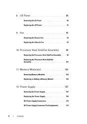
8 I/O Panel 89 Removing the I/O Panel 89 Replacing the I/O Panel 91 9 Fan 93 Removing the Chassis Fan 93 Replacing the Chassis Fan 97 10 Processor Heat Sink/Fan Assembly . . . 99 Removing the Processor Heat Sink/Fan Assembly . . . 99 Replacing the Processor Heat Sink/Fan Assembly 101 11 Memory Module(s 103 Removing Memory Modules 103 Replacing or Adding a Memory Module 104 12 Power Supply 107 Removing the Power Supply 107 Replacing the Power Supply 109 DC Power Supply Connectors 110 DC Power Supply Connector Pin Assignments . . . . 112 6 Contents
8 I/O Panel 89 Removing the I/O Panel 89 Replacing the I/O Panel 91 9 Fan 93 Removing the Chassis Fan 93 Replacing the Chassis Fan 97 10 Processor Heat Sink/Fan Assembly . . . 99 Removing the Processor Heat Sink/Fan Assembly . . . 99 Replacing the Processor Heat Sink/Fan Assembly 101 11 Memory Module(s 103 Removing Memory Modules 103 Replacing or Adding a Memory Module 104 12 Power Supply 107 Removing the Power Supply 107 Replacing the Power Supply 109 DC Power Supply Connectors 110 DC Power Supply Connector Pin Assignments . . . . 112 6 Contents
Service Manual
Page 37
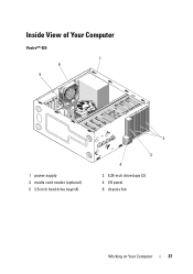
Inside View of Your Computer Vostro™ 420 1 6 5 1 power supply 3 media card reader (optional) 5 3.5-inch hard drive bays (4) 2 3 4 2 5.25-inch drive bays (3) 4 I/O panel 6 chassis fan Working on Your Computer 37
Inside View of Your Computer Vostro™ 420 1 6 5 1 power supply 3 media card reader (optional) 5 3.5-inch hard drive bays (4) 2 3 4 2 5.25-inch drive bays (3) 4 I/O panel 6 chassis fan Working on Your Computer 37
Service Manual
Page 38
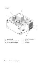
Vostro 220 1 6 5 2 3 1 power supply 3 media card reader (optional) 5 3.5-inch hard drive bays (2) 4 2 5.25-inch drive bays (2) 4 I/O panel 6 chassis fan 38 Working on Your Computer
Vostro 220 1 6 5 2 3 1 power supply 3 media card reader (optional) 5 3.5-inch hard drive bays (2) 4 2 5.25-inch drive bays (2) 4 I/O panel 6 chassis fan 38 Working on Your Computer
Service Manual
Page 39
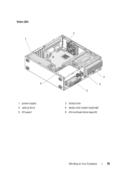
Vostro 220s 2 1 6 ' 1 power supply 3 optical drive 5 I/O panel 3 4 5 2 chassis fan 4 media card reader (optional) 6 3.5-inch hard drive bays (2) Working on Your Computer 39
Vostro 220s 2 1 6 ' 1 power supply 3 optical drive 5 I/O panel 3 4 5 2 chassis fan 4 media card reader (optional) 6 3.5-inch hard drive bays (2) Working on Your Computer 39
Service Manual
Page 107
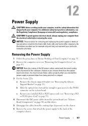
...NOTICE: Note the routing of the computer chassis. Removing the Power Supply 1 Follow the procedures in the computer chassis as you reinstall the power supply to the PWR1 connector on the system board. the illustrations provided are for the Vostro 420, Vostro 220, and Vostro 220s computers; b Slide the optical drive forward far enough to gain.... c Remove any installed PCI or PCI Express cards (see "Removing a PCI or PCI Express Card" on page 59). 4 Disconnect the DC power cables from the system board (see the Regulatory Compliance Homepage at www.dell.com/regulatory_compliance.
...NOTICE: Note the routing of the computer chassis. Removing the Power Supply 1 Follow the procedures in the computer chassis as you reinstall the power supply to the PWR1 connector on the system board. the illustrations provided are for the Vostro 420, Vostro 220, and Vostro 220s computers; b Slide the optical drive forward far enough to gain.... c Remove any installed PCI or PCI Express cards (see "Removing a PCI or PCI Express Card" on page 59). 4 Disconnect the DC power cables from the system board (see the Regulatory Compliance Homepage at www.dell.com/regulatory_compliance.
Service Manual
Page 108
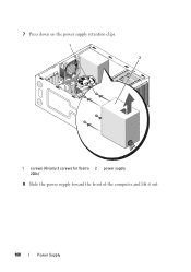
7 Press down on the power supply retention clips. 1 2 1 screws (4) (only 3 screws for Vostro 2 power supply 220s) 8 Slide the power supply toward the front of the computer and lift it out. 108 Power Supply
7 Press down on the power supply retention clips. 1 2 1 screws (4) (only 3 screws for Vostro 2 power supply 220s) 8 Slide the power supply toward the front of the computer and lift it out. 108 Power Supply
Service Manual
Page 109
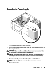
... to replace and tighten all cable connections to ensure that secure the power supply to the back of the grounding system. NOTICE: Route the DC power cables as these screws are secure. 4 For the Vostro 220s: Power Supply 109 NOTE: Double-check all screws may cause electrical shock as you insert them into place. 2 Replace and tighten...
... to replace and tighten all cable connections to ensure that secure the power supply to the back of the grounding system. NOTICE: Route the DC power cables as these screws are secure. 4 For the Vostro 220s: Power Supply 109 NOTE: Double-check all screws may cause electrical shock as you insert them into place. 2 Replace and tighten...
Service Manual
Page 110
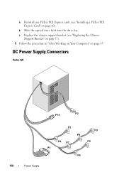
b Slide the optical drive back into the drive bay. a Reinstall any PCI or PCI Express cards (see "Replacing the Chassis Support Bracket" on page 57). 5 Follow the procedure in "After Working on Your Computer" on page 60). DC Power Supply Connectors Vostro 420 P10 P2 P3 P9 P8 P4 P7 P5 P1 P6 110 Power Supply c Replace the chassis support bracket (see "Installing a PCI or PCI Express Card" on page 45.
b Slide the optical drive back into the drive bay. a Reinstall any PCI or PCI Express cards (see "Replacing the Chassis Support Bracket" on page 57). 5 Follow the procedure in "After Working on Your Computer" on page 60). DC Power Supply Connectors Vostro 420 P10 P2 P3 P9 P8 P4 P7 P5 P1 P6 110 Power Supply c Replace the chassis support bracket (see "Installing a PCI or PCI Express Card" on page 45.

Service Manual
Page 113
Pin Number 5 6 7 8 9 10 11 12 13 14 15 16 17 18 19 20 21 22 23 24 Signal name RTN 5 V RTN POK 5 V AUX +12 V +12 V 3.3 V 3.3 V -12 V RTN PS_ON RTN RTN RTN OPEN 5 V 5 V 5 V RTN Wire Color Black Red Black Gray Purple Yellow Yellow Orange Orange Blue Black Green Black Black Black Wire Size 20 AWG 20 AWG 20 AWG 22 AWG 20 AWG 20 AWG 20 AWG 20 AWG 20 AWG 22 AWG 20 AWG 22 AWG 20 AWG 20 AWG 20 AWG Red Red Red Black 20 AWG 20 AWG 20 AWG 20 AWG DC Power Connector P2 3 4 1 2 Pin Number Signal Name 1 GND 18-AWG Wire Black Power Supply 113
Pin Number 5 6 7 8 9 10 11 12 13 14 15 16 17 18 19 20 21 22 23 24 Signal name RTN 5 V RTN POK 5 V AUX +12 V +12 V 3.3 V 3.3 V -12 V RTN PS_ON RTN RTN RTN OPEN 5 V 5 V 5 V RTN Wire Color Black Red Black Gray Purple Yellow Yellow Orange Orange Blue Black Green Black Black Black Wire Size 20 AWG 20 AWG 20 AWG 22 AWG 20 AWG 20 AWG 20 AWG 20 AWG 20 AWG 22 AWG 20 AWG 22 AWG 20 AWG 20 AWG 20 AWG Red Red Red Black 20 AWG 20 AWG 20 AWG 20 AWG DC Power Connector P2 3 4 1 2 Pin Number Signal Name 1 GND 18-AWG Wire Black Power Supply 113

Service Manual
Page 114
Pin Number 2 3 4 Signal Name GND +12 VADC +12 VADC 18-AWG Wire Black Yellow Yellow DC Power Connectors P3, P4, P5, P6, P7, and P8 Pin Number 1 2 3 4 5 Signal name +3.3 VDC GND +5 VDC GND +12 VBDC DC Power Connector P9 18-AWG Wire Orange Black Red Black White 4 321 Pin Number Signal Name 1 +5 VDC 2 GND 3 GND 4 +12 VADC 22-AWG Wire Red Black Black Yellow 114 Power Supply
Pin Number 2 3 4 Signal Name GND +12 VADC +12 VADC 18-AWG Wire Black Yellow Yellow DC Power Connectors P3, P4, P5, P6, P7, and P8 Pin Number 1 2 3 4 5 Signal name +3.3 VDC GND +5 VDC GND +12 VBDC DC Power Connector P9 18-AWG Wire Orange Black Red Black White 4 321 Pin Number Signal Name 1 +5 VDC 2 GND 3 GND 4 +12 VADC 22-AWG Wire Red Black Black Yellow 114 Power Supply

Service Manual
Page 115
DC Power Connector P10 Pin Number Signal Name 1 +12 VDC 2 +12 VDC 3 +12 VDC 4 GND 5 GND 6 GND 22-AWG Wire Yellow Yellow Yellow Black Black Black Power Supply 115
DC Power Connector P10 Pin Number Signal Name 1 +12 VDC 2 +12 VDC 3 +12 VDC 4 GND 5 GND 6 GND 22-AWG Wire Yellow Yellow Yellow Black Black Black Power Supply 115


