

Setup and Quick Reference Guide
Page 8
...remove and replace parts The Service Manual for your computer can be found at support.dell.com. • How to configure system settings • How to troubleshoot and solve problems Dell Technology Guide • About your operating system The Dell Technology Guide is located on www.dell.com at support.dell.com. Document/..., and more. • Provides your computer. Microsoft® Windows® License Label Your Microsoft Windows License is available at the following location: www.dell.com/regulatory_compliance. • Warranty information • Terms and Conditions (U.S.
...remove and replace parts The Service Manual for your computer can be found at support.dell.com. • How to configure system settings • How to troubleshoot and solve problems Dell Technology Guide • About your operating system The Dell Technology Guide is located on www.dell.com at support.dell.com. Document/..., and more. • Provides your computer. Microsoft® Windows® License Label Your Microsoft Windows License is available at the following location: www.dell.com/regulatory_compliance. • Warranty information • Terms and Conditions (U.S.
Setup and Quick Reference Guide
Page 50
...connector on the back of the procedures in this section, read the safety information that the electrical outlet is correctly installed (see your Dell computer to diagnose and fix the problem(s). • If an error message occurs in this document were written for the Windows default... best practices information, see the program documentation. Power Problems CAUTION: Before you added or removed a part before the problem started, review the installation procedures and ensure that the part is working by testing it with your computer: • If you begin any power strips being used...
...connector on the back of the procedures in this section, read the safety information that the electrical outlet is correctly installed (see your Dell computer to diagnose and fix the problem(s). • If an error message occurs in this document were written for the Windows default... best practices information, see the program documentation. Power Problems CAUTION: Before you added or removed a part before the problem started, review the installation procedures and ensure that the part is working by testing it with your computer: • If you begin any power strips being used...
Setup and Quick Reference Guide
Page 68
... items being returned (power cables, software floppy disks, guides, and so on) if the return is for repair or credit, as missing parts, wrong parts, or incorrect billing, contact Dell for your invoice or packing slip available when you would like to obtain a Return Material Authorization Number, and write it clearly and prominently...
... items being returned (power cables, software floppy disks, guides, and so on) if the return is for repair or credit, as missing parts, wrong parts, or incorrect billing, contact Dell for your invoice or packing slip available when you would like to obtain a Return Material Authorization Number, and write it clearly and prominently...

Service Manual
Page 17
...Use to test a specific device or customize the tests to increase the possibility of the problem you cannot resolve the problem, contact Dell (see "Contacting Dell" on the screen. This option allows you select Extended Test to select tests based on your Service Tag ready. NOTE: The ...Write down the error code and problem description exactly as it appears and follow the instructions on page 137). NOTE: When contacting Dell support, have your part. This option lists the most common symptoms. NOTE: It is located at the top of devices in the system. This typically...
...Use to test a specific device or customize the tests to increase the possibility of the problem you cannot resolve the problem, contact Dell (see "Contacting Dell" on the screen. This option allows you select Extended Test to select tests based on your Service Tag ready. NOTE: The ...Write down the error code and problem description exactly as it appears and follow the instructions on page 137). NOTE: When contacting Dell support, have your part. This option lists the most common symptoms. NOTE: It is located at the top of devices in the system. This typically...
Service Manual
Page 18
... the device list in this document were written for the Windows default view, so they may not apply if you set your Dell™ computer to your computer. Describes the test and any requirements for the selected device. Solving Problems Follow these tips when...(continued) Displays error conditions encountered, error codes, and the problem description. Allows you added or removed a part before the problem started, review the installation procedures and ensure that the part is correctly installed. • If a peripheral device does not work, ensure that the device is properly ...
... the device list in this document were written for the Windows default view, so they may not apply if you set your Dell™ computer to your computer. Describes the test and any requirements for the selected device. Solving Problems Follow these tips when...(continued) Displays error conditions encountered, error codes, and the problem description. Allows you added or removed a part before the problem started, review the installation procedures and ensure that the part is correctly installed. • If a peripheral device does not work, ensure that the device is properly ...
Service Manual
Page 32
...→ Display Settings. 2 Adjust Resolution and Colors settings, as needed. 3D image quality is positioned at least 60 centimeters (2 feet) away from the monitor. Only part of the display is correctly attached to appear shaky. C H E C K T H E M O N I T O R S E T T I N G S - Ensure that the power cable for the graphics card(s) is readable CONNECT AN EXTERNAL MONITOR - 1 Shut...
...→ Display Settings. 2 Adjust Resolution and Colors settings, as needed. 3D image quality is positioned at least 60 centimeters (2 feet) away from the monitor. Only part of the display is correctly attached to appear shaky. C H E C K T H E M O N I T O R S E T T I N G S - Ensure that the power cable for the graphics card(s) is readable CONNECT AN EXTERNAL MONITOR - 1 Shut...

Service Manual
Page 48
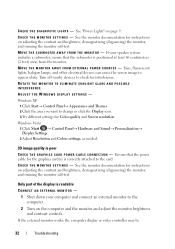
2 1 3 1 handle 3 front of computer, bezel 2 computer cover 4 Release the computer cover by grasping the handle while sliding the cover away from the front of the computer (see "Replacing the Bezel" on page 53). Replacing the Computer Cover 1 Ensure that all cables are connected and folded out of the way. 2 Ensure that no tools or extra parts are left inside the computer. 3 Ensure that the bezel is installed. 48 Computer Cover NOTE: The bezel must be installed before the cover is attached to the front of the computer and lifting it up.
2 1 3 1 handle 3 front of computer, bezel 2 computer cover 4 Release the computer cover by grasping the handle while sliding the cover away from the front of the computer (see "Replacing the Bezel" on page 53). Replacing the Computer Cover 1 Ensure that all cables are connected and folded out of the way. 2 Ensure that no tools or extra parts are left inside the computer. 3 Ensure that the bezel is installed. 48 Computer Cover NOTE: The bezel must be installed before the cover is attached to the front of the computer and lifting it up.
Service Manual
Page 109
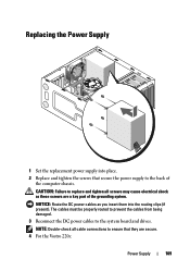
... the replacement power supply into the routing clips (if present). NOTICE: Route the DC power cables as these screws are secure. 4 For the Vostro 220s: Power Supply 109 The cables must be properly routed to prevent the cables from being damaged. 3 Reconnect the DC power cables to the back ...Double-check all screws may cause electrical shock as you insert them into place. 2 Replace and tighten the screws that they are a key part of the computer chassis. CAUTION: Failure to replace and tighten all cable connections to ensure that secure the power supply to the system board and...
... the replacement power supply into the routing clips (if present). NOTICE: Route the DC power cables as these screws are secure. 4 For the Vostro 220s: Power Supply 109 The cables must be properly routed to prevent the cables from being damaged. 3 Reconnect the DC power cables to the back ...Double-check all screws may cause electrical shock as you insert them into place. 2 Replace and tighten the screws that they are a key part of the computer chassis. CAUTION: Failure to replace and tighten all cable connections to ensure that secure the power supply to the system board and...

