DWC-1000 User's Guide
Page 13
...notify your wireless controller: • D-Link DWL-3600, DWL-6600, and/or DWL-8600 access points • A Power over Ethernet (PoE) switch • A personal computer (PC) with one of the web browsers on page 27 installed 13 DWC-1000 Wireless Controller User's Guide Confirm that... Required Tools and Information You will need the following additional items to install your authorized D-Link representative. Package Contents Each wireless controller package contains the following items: • One D-Link DWC-1000 Wireless Controller • One power cord • One RJ-45 to DB-9 console ...
...notify your wireless controller: • D-Link DWL-3600, DWL-6600, and/or DWL-8600 access points • A Power over Ethernet (PoE) switch • A personal computer (PC) with one of the web browsers on page 27 installed 13 DWC-1000 Wireless Controller User's Guide Confirm that... Required Tools and Information You will need the following additional items to install your authorized D-Link representative. Package Contents Each wireless controller package contains the following items: • One D-Link DWC-1000 Wireless Controller • One power cord • One RJ-45 to DB-9 console ...
DWC-1000 User's Guide
Page 14
...a Location Selecting the proper location for the wireless controller is not controlled by a wall switch that generates heat or will block the free flow of air through the wireless controller's ...an access point-to-client connectivity test to variations in Appendix A. To ensure optimum performance, D-LINK recommends that might require dense access point coverage. • Determine the indoor propagation of RF signals...RF behavior, and detect both sides and rear of the site to the outlet. 14 DWC-1000 Wireless Controller User's Guide The ideal location should enable you to it. • ...
...a Location Selecting the proper location for the wireless controller is not controlled by a wall switch that generates heat or will block the free flow of air through the wireless controller's ...an access point-to-client connectivity test to variations in Appendix A. To ensure optimum performance, D-LINK recommends that might require dense access point coverage. • Determine the indoor propagation of RF signals...RF behavior, and detect both sides and rear of the site to the outlet. 14 DWC-1000 Wireless Controller User's Guide The ideal location should enable you to it. • ...
DWC-1000 User's Guide
Page 16
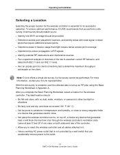
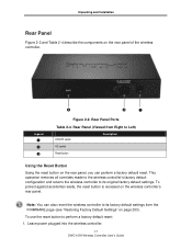
USB LEDs LED USB LED Color Green Description ON = link is defective and firmware upgrades have failed. see Table 2-2. Two USB 2.0 Ports Two Universal Serial Bus (USB) 2.0 ports are provided for connecting USB flash ... connect Ethernet devices such as computers, switches, and hubs. OFF= wireless controller is located on the far left ) and Link LED (right) - ON = power-on or power-off . Power LED Facing the front of the wireless controller's power-on process in recovery mode following a crash. 16 DWC-1000 Wireless Controller User's Guide This...
USB LEDs LED USB LED Color Green Description ON = link is defective and firmware upgrades have failed. see Table 2-2. Two USB 2.0 Ports Two Universal Serial Bus (USB) 2.0 ports are provided for connecting USB flash ... connect Ethernet devices such as computers, switches, and hubs. OFF= wireless controller is located on the far left ) and Link LED (right) - ON = power-on or power-off . Power LED Facing the front of the wireless controller's power-on process in recovery mode following a crash. 16 DWC-1000 Wireless Controller User's Guide This...
DWC-1000 User's Guide
Page 17
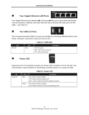
... wireless controller to perform a factory default reset: 1. Leave power plugged into the wireless controller. 17 DWC-1000 Wireless Controller User's Guide To use the reset button to its factory default settings from Right to Left) ON/OFF switch Description AC socket Reset button Using the Reset Button Using the reset button on page...
... wireless controller to perform a factory default reset: 1. Leave power plugged into the wireless controller. 17 DWC-1000 Wireless Controller User's Guide To use the reset button to its factory default settings from Right to Left) ON/OFF switch Description AC socket Reset button Using the Reset Button Using the reset button on page...
DWC-1000 User's Guide
Page 19
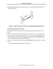
... Figure 2-4). Your installation should resemble the one of the wireless controller ports labeled LAN (1-4) to the network or directly to the instructions in Figure 2-5. 19 DWC-1000 Wireless Controller User's Guide Connect one in their documentation. 2. Install the switch and access points according to a PC.
... Figure 2-4). Your installation should resemble the one of the wireless controller ports labeled LAN (1-4) to the network or directly to the instructions in Figure 2-5. 19 DWC-1000 Wireless Controller User's Guide Connect one in their documentation. 2. Install the switch and access points according to a PC.
DWC-1000 User's Guide
Page 20
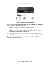
... the supplied power cord, connect the wireless controller to the left of the front panel USB ports goes ON. Set the ON/OFF switch on page 212. 20 DWC-1000 Wireless Controller User's Guide Option2 = WAN or DMZ port for connecting to the ON position. The green Power LED to a working AC outlet...
... the supplied power cord, connect the wireless controller to the left of the front panel USB ports goes ON. Set the ON/OFF switch on page 212. 20 DWC-1000 Wireless Controller User's Guide Option2 = WAN or DMZ port for connecting to the ON position. The green Power LED to a working AC outlet...

DWC-1000 User's Guide
Page 21
...In this configuration: • The access points and wireless controller are connected in a variety of the PoE switch provides Internet access. • The access points and wireless controller are connected to a PoE switch. • The uplink of network configurations. This configuration allows you to send data over Ethernet (PoE... controller. • The access points and wireless controller are configured for WEP or WPA. • The operating system on the switch and wireless controller. Example of Connecting to a Secured Network 21 DWC-1000 Wireless Controller User's Guide
...In this configuration: • The access points and wireless controller are connected in a variety of the PoE switch provides Internet access. • The access points and wireless controller are connected to a PoE switch. • The uplink of network configurations. This configuration allows you to send data over Ethernet (PoE... controller. • The access points and wireless controller are configured for WEP or WPA. • The operating system on the switch and wireless controller. Example of Connecting to a Secured Network 21 DWC-1000 Wireless Controller User's Guide
DWC-1000 User's Guide
Page 22
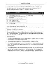
... access to desired settings, including security. 3. Authenticating to an Authentication Server Web authentication is a feature that denies a client access to a Layer 3 switch or router that must be configured.) 22 DWC-1000 Wireless Controller User's Guide Step Configuration Path in the same subnet and use the procedure below to configure the wireless controller for...
... access to desired settings, including security. 3. Authenticating to an Authentication Server Web authentication is a feature that denies a client access to a Layer 3 switch or router that must be configured.) 22 DWC-1000 Wireless Controller User's Guide Step Configuration Path in the same subnet and use the procedure below to configure the wireless controller for...
DWC-1000 User's Guide
Page 24
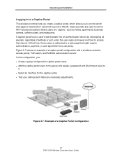
... all packets, regardless of a captive portal configuration with a wireless controller, access points, PoE switch, and RADIUS authentication server. At that might require authentication, payment, or user agreement to access the Internet. Example of a Captive Portal Configuration 24 DWC-1000 Wireless Controller User's Guide In this configuration, you to control which allows you : •...
... all packets, regardless of a captive portal configuration with a wireless controller, access points, PoE switch, and RADIUS authentication server. At that might require authentication, payment, or user agreement to access the Internet. Example of a Captive Portal Configuration 24 DWC-1000 Wireless Controller User's Guide In this configuration, you to control which allows you : •...
DWC-1000 User's Guide
Page 56
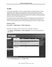
...to be isolated from the general LAN. Click SETUP > VLAN Settings > VLAN Configuration. The primary use of a device in a switched network. VLAN filtering is particularly useful to limit broadcast packets of VLANs is disabled. To enable it: 1. VLANs separate devices into ... VLAN Configuration By default, the wireless controller's VLAN function is to and from that traffic to split large switched networks, which are large broadcast domains. Under VLAN Configuration, check Enable VLAN. 56 DWC-1000 Wireless Controller User's Guide The VLAN CONFIGURATION page appears. 2.
...to be isolated from the general LAN. Click SETUP > VLAN Settings > VLAN Configuration. The primary use of a device in a switched network. VLAN filtering is particularly useful to limit broadcast packets of VLANs is disabled. To enable it: 1. VLANs separate devices into ... VLAN Configuration By default, the wireless controller's VLAN function is to and from that traffic to split large switched networks, which are large broadcast domains. Under VLAN Configuration, check Enable VLAN. 56 DWC-1000 Wireless Controller User's Guide The VLAN CONFIGURATION page appears. 2.
DWC-1000 User's Guide
Page 76
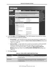
Then use the adjacent drop-down list to the secondary Option port. 76 DWC-1000 Wireless Controller User's Guide Under Port Mode, click Load Balancing. Round Robin - If you select this setting, complete the Option Failure... used for all connections until the bandwidth threshold is used for new connections. a single Option link is reached, after which the wireless controller switches to the Internet alternate between available links. Table 4-6. Enter the maximum bandwidth tolerable by the Primary Option. Spillover Mode - Advanced Configuration Settings 2. If you ...
Then use the adjacent drop-down list to the secondary Option port. 76 DWC-1000 Wireless Controller User's Guide Under Port Mode, click Load Balancing. Round Robin - If you select this setting, complete the Option Failure... used for all connections until the bandwidth threshold is used for new connections. a single Option link is reached, after which the wireless controller switches to the Internet alternate between available links. Table 4-6. Enter the maximum bandwidth tolerable by the Primary Option. Spillover Mode - Advanced Configuration Settings 2. If you ...
DWC-1000 User's Guide
Page 212
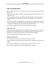
...Ethernet connection is ON for any of events should occur: 1. If the error persists, please contact D-Link technical support. Be sure power is applied to the connected switch and that are connected. This indicates that the Ethernet cable connections are secure at the wireless controller ...that the right LAN port LED is made: 1. Troubleshooting LED Troubleshooting After you are using the correct cables (straight-through or crossover). 212 DWC-1000 Wireless Controller User's Guide If a port is connected to the left of the USB ports is OFF. After approximately 2 minutes, verify ...
...Ethernet connection is ON for any of events should occur: 1. If the error persists, please contact D-Link technical support. Be sure power is applied to the connected switch and that are connected. This indicates that the Ethernet cable connections are secure at the wireless controller ...that the right LAN port LED is made: 1. Troubleshooting LED Troubleshooting After you are using the correct cables (straight-through or crossover). 212 DWC-1000 Wireless Controller User's Guide If a port is connected to the left of the USB ports is OFF. After approximately 2 minutes, verify ...
User Manual
Page 6
...URLs ...214 7.10.3 Blocked Keywords ...215 7.10.4 Export Web Filter ...216 7.11 IP/MAC Binding ...217 7.12 RADIUS Settings...218 7.13 Switch Settings ...220 7.14 Protecting from Internet Attacks 221 Chapter 8. Wireless Controller User Manual 6.2.5 6.2.6 6.2.7 6.3 6.3.1 6.3.2 6.3.3 6.4 6.4.1 6.4.2 6.4.3... L2TP and PP TP Option 167 Option Configuration in an IP v6 Network 169 Checking Option Status 172 Features with Multipl e Option Links 175 Auto Failover ...175 Load Balancing ...176 Protocol Bindings ...178 Routing Configuration...180 Routing Mode ...180 Dynamic Routing (RIP 183 Static...
...URLs ...214 7.10.3 Blocked Keywords ...215 7.10.4 Export Web Filter ...216 7.11 IP/MAC Binding ...217 7.12 RADIUS Settings...218 7.13 Switch Settings ...220 7.14 Protecting from Internet Attacks 221 Chapter 8. Wireless Controller User Manual 6.2.5 6.2.6 6.2.7 6.3 6.3.1 6.3.2 6.3.3 6.4 6.4.1 6.4.2 6.4.3... L2TP and PP TP Option 167 Option Configuration in an IP v6 Network 169 Checking Option Status 172 Features with Multipl e Option Links 175 Auto Failover ...175 Load Balancing ...176 Protocol Bindings ...178 Routing Configuration...180 Routing Mode ...180 Dynamic Routing (RIP 183 Static...
User Manual
Page 12
... 123: Switch settings ...220 Figure 124: Protecting the controller and LA N from internet attacks 222 Figure 125: Example of Gateway-to-Gateway IPsec VPN tunnel using two DWC controllers connected to the Int ernet ...224 Figure 126: Example of three IPsec client connections to the DWC-1000 242 Figure... 137: List of clientless SSL VPN connections to the internal network through the DWC IPsec gateway ...225 Figure 127: VPN Wizard launch screen ...226 Figure 128: IPsec policy ...
... 123: Switch settings ...220 Figure 124: Protecting the controller and LA N from internet attacks 222 Figure 125: Example of Gateway-to-Gateway IPsec VPN tunnel using two DWC controllers connected to the Int ernet ...224 Figure 126: Example of three IPsec client connections to the DWC-1000 242 Figure... 137: List of clientless SSL VPN connections to the internal network through the DWC IPsec gateway ...225 Figure 127: VPN Wizard launch screen ...226 Figure 128: IPsec policy ...
User Manual
Page 222
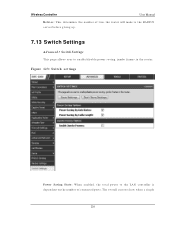
Th e o v erall cu rren t d raw wh en a s in t h e ro u t er. Wireless Controller User Manual Retri es : Th is d et ermin es t h e n u mb er o f t ries t h e ro u t er will make t o t h e RA DIUS s erver before giving up. 7.13 Switch Settings Advanced > Switch Settings Th is p ag e allo ws u s er t o en ab le/ d is d ep en d ent o n t h e n umb er o f co n n ected p o rts. Figure 123: Switch s e ttings Power S avi ng S tate: W h en en ab led , t h e t o t al p o wer t o t h e LA N co n t ro ller is ab le p o wer s av in g , ju mb o frames in g le 220
Th e o v erall cu rren t d raw wh en a s in t h e ro u t er. Wireless Controller User Manual Retri es : Th is d et ermin es t h e n u mb er o f t ries t h e ro u t er will make t o t h e RA DIUS s erver before giving up. 7.13 Switch Settings Advanced > Switch Settings Th is p ag e allo ws u s er t o en ab le/ d is d ep en d ent o n t h e n umb er o f co n n ected p o rts. Figure 123: Switch s e ttings Power S avi ng S tate: W h en en ab led , t h e t o t al p o wer t o t h e LA N co n t ro ller is ab le p o wer s av in g , ju mb o frames in g le 220

