Series 1000 Brochure
Page 1
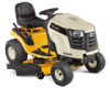
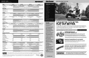
...one else can deliver. Prove it so easy to maneuver around landscaping and enjoy all new Cub Cadet Series 1000 Tractors. and dent-resistant high-impact ABS Steel fender w/twin rear fender ...QuickAttach™ in U.S.A. 12/12 © 2013 Cub Cadet Lawn and garden tractors SERIES 1000 LTX 1040 LTX 1042 KW LTX 1045 LTX 1046 LTX 1046 KW LTX 1050 LTX 1050 KW LGT 1050 LGT 1054 LGTX 1050 LGTX ... addition of 5 years or 500 hours, whichever occurs first, for advertisement purposes only. MOWer DECK Cutting Width/Blades Deck Cutting Height deck Construction Deck Drive System Anti-scalping Mulch Kit...
...one else can deliver. Prove it so easy to maneuver around landscaping and enjoy all new Cub Cadet Series 1000 Tractors. and dent-resistant high-impact ABS Steel fender w/twin rear fender ...QuickAttach™ in U.S.A. 12/12 © 2013 Cub Cadet Lawn and garden tractors SERIES 1000 LTX 1040 LTX 1042 KW LTX 1045 LTX 1046 LTX 1046 KW LTX 1050 LTX 1050 KW LGT 1050 LGT 1054 LGTX 1050 LGTX ... addition of 5 years or 500 hours, whichever occurs first, for advertisement purposes only. MOWer DECK Cutting Width/Blades Deck Cutting Height deck Construction Deck Drive System Anti-scalping Mulch Kit...

LTX 1042 KW Operator's Manual
Page 26
... in Figure 7-7. Reconnect the deck lift arms. See Figure 7-3. 2. See Figure 7-4. See Figure 7-8. Cutting Blades Figure 7-7 5. To place the new belt, begin by using heavy gloves when grasping the blade 6. WARNING! Reinstall the deck as follows: To remove the blades, proceed as a stabilizer...not operate the machine 8. Place a block of wood between the center deck housing c. WARNING! See Figure 7-1. With the deck beneath the mower frame, attach the 1. Remove the deck from around the two outer spindle pulleys as shown in this section) then gently flip the deck ...
... in Figure 7-7. Reconnect the deck lift arms. See Figure 7-3. 2. See Figure 7-4. See Figure 7-8. Cutting Blades Figure 7-7 5. To place the new belt, begin by using heavy gloves when grasping the blade 6. WARNING! Reinstall the deck as follows: To remove the blades, proceed as a stabilizer...not operate the machine 8. Place a block of wood between the center deck housing c. WARNING! See Figure 7-1. With the deck beneath the mower frame, attach the 1. Remove the deck from around the two outer spindle pulleys as shown in this section) then gently flip the deck ...

LTX 1042 KW Operator's Manual
Page 27
To properly sharpen the cutting blades, remove equal amounts of metal from the heavy side until it ) facing the ground when the mower is present, replace the blades with a part number stamped in it balances evenly. Always grind each cutting blade edge equally to cause cancer and reproductive ... on a vehicle (i.e. Figure 7-10 5. NOTE: When replacing the blade, be sure to install the blade with the side of the blade marked ''Bottom'' (or with new ones. Jump Starting WARNING! Start the tractor (as instructed in personal injury. WARNING! Do not allow cable clamps to between 70 ft-lbs and 90...
To properly sharpen the cutting blades, remove equal amounts of metal from the heavy side until it ) facing the ground when the mower is present, replace the blades with a part number stamped in it balances evenly. Always grind each cutting blade edge equally to cause cancer and reproductive ... on a vehicle (i.e. Figure 7-10 5. NOTE: When replacing the blade, be sure to install the blade with the side of the blade marked ''Bottom'' (or with new ones. Jump Starting WARNING! Start the tractor (as instructed in personal injury. WARNING! Do not allow cable clamps to between 70 ft-lbs and 90...

Operation Manual
Page 26
... are replaced. SECTION7-- r 4. See Fig. 7-6. 5. Replace the belt guard. Reinstall the deck as follows. With the deck beneath the mower frame, attach the stabilizer rod. See Fig. 7-4. orShreupt latcheementg.ine Proofftaenctd yoreumr ohvaends by routing the belt around the two spindle pulleys and... proceed as follows: a. 3. Remove the deck belt from around the two outer spindle pulleys as shown in Fig. 7-7. To place the new belt, begin by using heavy gloves when grasping the blade WARNING! See Fig. 7-5. b. Reattach the deck engage cable. ignition key before ...
... are replaced. SECTION7-- r 4. See Fig. 7-6. 5. Replace the belt guard. Reinstall the deck as follows. With the deck beneath the mower frame, attach the stabilizer rod. See Fig. 7-4. orShreupt latcheementg.ine Proofftaenctd yoreumr ohvaends by routing the belt around the two spindle pulleys and... proceed as follows: a. 3. Remove the deck belt from around the two outer spindle pulleys as shown in Fig. 7-7. To place the new belt, begin by using heavy gloves when grasping the blade WARNING! See Fig. 7-5. b. Reattach the deck engage cable. ignition key before ...

Operation Manual
Page 27
...-lNbs:. CAUTION: If removing the battery, disconnect the NEGATIVE (Black) wire from the heavy side until it ) facing the ground when the mower is present, replace the blades with new ones. Start the tractor (as a stabilizer. Place a block of the jumper battery. 4. Connect the positive (+) cable to cause cancer and reproductive harm...
...-lNbs:. CAUTION: If removing the battery, disconnect the NEGATIVE (Black) wire from the heavy side until it ) facing the ground when the mower is present, replace the blades with new ones. Start the tractor (as a stabilizer. Place a block of the jumper battery. 4. Connect the positive (+) cable to cause cancer and reproductive harm...

Operation Manual
Page 98
Place the belt into the engine pulley. r 4. Remount the belt guards removed earlier. 10. With the deck beneath the mower frame, attach the stabilizer rod. To remove the blades, proceed as follows: a. SERVICE See Fig. 7-6. 5. Periodically inspect the blade and/or spindle for _ shaArRpeNnINinGg ! PTO ... two deck idler pulleys. 6. See Fig. 7-8. Carefully remove the deck belt from around the two deck idler pulleys as shown in Fig. 7-7. 8. To place the new belt, begin by using heavy gloves when grasping the blade WARNING! See Fig. 7-5.
Place the belt into the engine pulley. r 4. Remount the belt guards removed earlier. 10. With the deck beneath the mower frame, attach the stabilizer rod. To remove the blades, proceed as follows: a. SERVICE See Fig. 7-6. 5. Periodically inspect the blade and/or spindle for _ shaArRpeNnINinGg ! PTO ... two deck idler pulleys. 6. See Fig. 7-8. Carefully remove the deck belt from around the two deck idler pulleys as shown in Fig. 7-7. 8. To place the new belt, begin by using heavy gloves when grasping the blade WARNING! See Fig. 7-5.

Operation Manual
Page 99
...:When replacing the blade, be sure to install the blade with the side of California to the State of the blade marked "Bottom" (or with new ones. See Fig. 7-10. Figure 7-10 SECTION7 -- Connect the positive (+) cable to positive (+) post of the blades along the cutting edges, ... of connection. To properly sharpen the cutting blades, remove equal amounts of metal from the heavy side until it ) facing the ground when the mower is present, replace the blades with a part number stamped in it balances evenly. A poorly balanced blade will cause excessive vibration, may cause damage...
...:When replacing the blade, be sure to install the blade with the side of California to the State of the blade marked "Bottom" (or with new ones. See Fig. 7-10. Figure 7-10 SECTION7 -- Connect the positive (+) cable to positive (+) post of the blades along the cutting edges, ... of connection. To properly sharpen the cutting blades, remove equal amounts of metal from the heavy side until it ) facing the ground when the mower is present, replace the blades with a part number stamped in it balances evenly. A poorly balanced blade will cause excessive vibration, may cause damage...


