
Hardware Programming Guide
Page 2
... SOFTWARE, (2) LICENSEE SHALL USE THE MANUAL AND/OR SOFTWARE ONLY FOR THE PURPOSE OF DEVELOPING LICENSEE APPLICATIONS COMPATIBLE WITH CREATIVE'S SOUND BLASTER SERIES OF PRODUCTS, UNLESS OTHERWISE AGREED TO BY FURTHER WRITTEN AGREEMENT FROM CREATIVE TECHNOLOGY LTD.; AND, (3) LICENSEE SHALL NOT DISTRIBUTE OR COPY THE MANUAL FOR ANY REASON OR BY ANY MEANS (INCLUDING...
... SOFTWARE, (2) LICENSEE SHALL USE THE MANUAL AND/OR SOFTWARE ONLY FOR THE PURPOSE OF DEVELOPING LICENSEE APPLICATIONS COMPATIBLE WITH CREATIVE'S SOUND BLASTER SERIES OF PRODUCTS, UNLESS OTHERWISE AGREED TO BY FURTHER WRITTEN AGREEMENT FROM CREATIVE TECHNOLOGY LTD.; AND, (3) LICENSEE SHALL NOT DISTRIBUTE OR COPY THE MANUAL FOR ANY REASON OR BY ANY MEANS (INCLUDING...
Hardware Programming Guide
Page 3
... involved in the manual and software even if Creative Technology Ltd. Information in lieu of International Business Machines Corporation. shall have no obligation to provide to you. All rights reserved. Sound Blaster, Sound Blaster Pro, Sound Blaster 16, and Wave Blaster are trademarks or registered trademarks of such errors and Creative Technology Ltd. IBM is a registered trademark of said...
... involved in the manual and software even if Creative Technology Ltd. Information in lieu of International Business Machines Corporation. shall have no obligation to provide to you. All rights reserved. Sound Blaster, Sound Blaster Pro, Sound Blaster 16, and Wave Blaster are trademarks or registered trademarks of such errors and Creative Technology Ltd. IBM is a registered trademark of said...
Hardware Programming Guide
Page 4
... Scope and Manual Organization...ix Document Conventions...x Determining User's Sound Blaster Card ...xii Determining User's Card Settings...xiii Chapter 1 Hardware Overview Anatomy of Sound Blaster Family of Audio Cards...1-2 Digital Sound Processor Chip...1-2 Mixer Chip...1-3 FM Synthesizer Chip...1-3 Bus Interface Chip...1-4 Advanced Signal Processor ...1-4 Block Diagrams for Sound Blaster Family of Audio Cards...1-6 Chapter 2 Introduction to DSP...
... Scope and Manual Organization...ix Document Conventions...x Determining User's Sound Blaster Card ...xii Determining User's Card Settings...xiii Chapter 1 Hardware Overview Anatomy of Sound Blaster Family of Audio Cards...1-2 Digital Sound Processor Chip...1-2 Mixer Chip...1-3 FM Synthesizer Chip...1-3 Bus Interface Chip...1-4 Advanced Signal Processor ...1-4 Block Diagrams for Sound Blaster Family of Audio Cards...1-6 Chapter 2 Introduction to DSP...

Hardware Programming Guide
Page 6
vi Contents Appendix A Sound Blaster I/O Address Maps SB1.5 I/O Address Map...A-2 SBMCV I/O Address Map ...A-3 SB2.0 I/O Address Map...A-4 SB2CD I/O Address Map...A-5 SBPRO I/O Address Map ...A-6 SBPRO MCV I/O Address Map...A-9 SB16 I/O Address Map...A-10 Appendix B File Format Creative Voice File (VOC) Format...B-2 Header Block...B-2 Data Block ...B-3 Creative ADPCM Wave Type Format...B-12 Appendix C Relevant Information Index
vi Contents Appendix A Sound Blaster I/O Address Maps SB1.5 I/O Address Map...A-2 SBMCV I/O Address Map ...A-3 SB2.0 I/O Address Map...A-4 SB2CD I/O Address Map...A-5 SBPRO I/O Address Map ...A-6 SBPRO MCV I/O Address Map...A-9 SB16 I/O Address Map...A-10 Appendix B File Format Creative Voice File (VOC) Format...B-2 Header Block...B-2 Data Block ...B-3 Creative ADPCM Wave Type Format...B-12 Appendix C Relevant Information Index

Hardware Programming Guide
Page 7
... of the Advanced Signal Processor...1-4 Block Diagram of the Sound Blaster 2.0...1-6 Block Diagram of the Sound Blaster 2.0 CD Interface ...1-7 Block Diagram of the Sound Blaster Pro...1-8 Block Diagram of the Sound Blaster 16 Advanced Signal Processing ...1-9 PCM sample size...3-2 Order ...12 Table A-13 Table A-14 Table A-15 Table A-16 Table A-17 DSP I/O Ports...2-2 DMA Operation Modes Supported...3-7 Digitized Sound Output Capabilities ...3-8 Digitized Sound Input Capabilities...3-9 MPU-401 I/O Ports...5-5 SB1.5 I/O Ports ...A-2 SB1.5 I/O Port Functions...A-2 SBMCV I/O Ports...A-3 SBMCV I/O ...
... of the Advanced Signal Processor...1-4 Block Diagram of the Sound Blaster 2.0...1-6 Block Diagram of the Sound Blaster 2.0 CD Interface ...1-7 Block Diagram of the Sound Blaster Pro...1-8 Block Diagram of the Sound Blaster 16 Advanced Signal Processing ...1-9 PCM sample size...3-2 Order ...12 Table A-13 Table A-14 Table A-15 Table A-16 Table A-17 DSP I/O Ports...2-2 DMA Operation Modes Supported...3-7 Digitized Sound Output Capabilities ...3-8 Digitized Sound Input Capabilities...3-9 MPU-401 I/O Ports...5-5 SB1.5 I/O Ports ...A-2 SB1.5 I/O Port Functions...A-2 SBMCV I/O Ports...A-3 SBMCV I/O ...
Hardware Programming Guide
Page 8
... carried out in three compressed formats: 8 to 4 bits, 8 to 3 bits, and 8 to and received from external MIDI devices. namely the Digital Sound Processor (DSP), Mixer chip, and MIDI Port. The MIDI Port on Sound Blaster cards conform to the main Creative-specific Sound Blaster hardware components; Through this port, MIDI messages can be transmitted to 2 bits.
... carried out in three compressed formats: 8 to 4 bits, 8 to 3 bits, and 8 to and received from external MIDI devices. namely the Digital Sound Processor (DSP), Mixer chip, and MIDI Port. The MIDI Port on Sound Blaster cards conform to the main Creative-specific Sound Blaster hardware components; Through this port, MIDI messages can be transmitted to 2 bits.
Hardware Programming Guide
Page 9
This manual also assumes you are familiar with changing the base I/O address, interrupt and DMA channels of the Sound Blaster cards. This manual is used in the appendix if you need more information on these assumptions. Some chapters in ... will list these subjects. Scope and Manual Organization This manual focuses on the Creative-specific hardware programming of the following chapters: Chapter 1, "Hardware Overview", gives an overview and functional block diagram of Sound Blaster cards. Refer to proceed until you have mastered the characteristics of microprocessors is ...
This manual also assumes you are familiar with changing the base I/O address, interrupt and DMA channels of the Sound Blaster cards. This manual is used in the appendix if you need more information on these assumptions. Some chapters in ... will list these subjects. Scope and Manual Organization This manual focuses on the Creative-specific hardware programming of the following chapters: Chapter 1, "Hardware Overview", gives an overview and functional block diagram of Sound Blaster cards. Refer to proceed until you have mastered the characteristics of microprocessors is ...
Hardware Programming Guide
Page 10
... detail. "Single-cycle" refers to the Single Transfer Mode, and "Auto-initialize" refers to the whole series of Sound Blaster cards. x Introduction Chapter 3, "Digitized Sound I/O Programming", describes the programming information for control of the other relevant materials. Chapter 6, "DSP Commands", describes the...to refer to the Auto-initialize Single Transfer Mode used to refer to you " refers to DMA mode digitized sound I /O Programming", discusses Sound Blaster MIDI Port and MPU-401 MIDI UART mode programming. Appendix B, "Relevant Information", lists the sources of the mixer...
... detail. "Single-cycle" refers to the Single Transfer Mode, and "Auto-initialize" refers to the whole series of Sound Blaster cards. x Introduction Chapter 3, "Digitized Sound I/O Programming", describes the programming information for control of the other relevant materials. Chapter 6, "DSP Commands", describes the...to refer to the Auto-initialize Single Transfer Mode used to refer to you " refers to DMA mode digitized sound I /O Programming", discusses Sound Blaster MIDI Port and MPU-401 MIDI UART mode programming. Appendix B, "Relevant Information", lists the sources of the mixer...
Hardware Programming Guide
Page 11
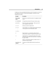
Italics may also be typed verbatim. It should not be used . / Sound Blaster Pro (SBPRO) Angle brackets in a command line indicate that the enclosed item is used for keywords or to locate and identify information easily, this manual: ...
Italics may also be typed verbatim. It should not be used . / Sound Blaster Pro (SBPRO) Angle brackets in a command line indicate that the enclosed item is used for keywords or to locate and identify information easily, this manual: ...
Hardware Programming Guide
Page 12
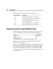
...00 2.01+ 3.xx 4.xx. Description This means DSPs with major version number 3. This means DSPs with major version number 1. Determining User's Sound Blaster Card Sound Blaster cards can read the value from I/O port 388h, two-operator cards will return a value of 06h, and four-operator cards will return ...a value of SBPRO. The table below lists the Sound Blaster cards and their DSP version numbers. The difference is in the subsequent chapters. xii Introduction The following DSP version notations will be ...
...00 2.01+ 3.xx 4.xx. Description This means DSPs with major version number 3. This means DSPs with major version number 1. Determining User's Sound Blaster Card Sound Blaster cards can read the value from I/O port 388h, two-operator cards will return a value of 06h, and four-operator cards will return ...a value of SBPRO. The table below lists the Sound Blaster cards and their DSP version numbers. The difference is in the subsequent chapters. xii Introduction The following DSP version notations will be ...
Hardware Programming Guide
Page 13
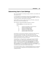
...variable specifies the base I /O port Note that d and h are jumper selectable to adopt, as follows: SET BLASTER=A220 I5 D1 [H5 M220 P330] where: A I D H M P specifies the Sound Blaster card's base I/O port specifies the interrupt request line specifies the 8-bit DMA channel specifies the 16-bit DMA ... after the = (equal) sign, but there must be run to configure the Sound Blaster 16 appropriately. We encourage developers to avoid conflicts with Sound Blaster 16 package must be set such that there is run, the BLASTER environment entries "Dd" and "Hh" must be the same as the card's ...
...variable specifies the base I /O port Note that d and h are jumper selectable to adopt, as follows: SET BLASTER=A220 I5 D1 [H5 M220 P330] where: A I D H M P specifies the Sound Blaster card's base I/O port specifies the interrupt request line specifies the 8-bit DMA channel specifies the 16-bit DMA ... after the = (equal) sign, but there must be run to configure the Sound Blaster 16 appropriately. We encourage developers to avoid conflicts with Sound Blaster 16 package must be set such that there is run, the BLASTER environment entries "Dd" and "Hh" must be the same as the card's ...
Hardware Programming Guide
Page 14
Chapter 1 Hardware Overview This chapter gives an overview of the hardware architecture of the Sound Blaster family of the Sound Blaster family cards and their functionalities will be discussed. Major building blocks of audio cards. This chapter also covers the anatomy and block diagrams of Sound Blaster family of audio cards. It is meant for developers who intend to do hardware level programming.
Chapter 1 Hardware Overview This chapter gives an overview of the hardware architecture of the Sound Blaster family of the Sound Blaster family cards and their functionalities will be discussed. Major building blocks of audio cards. This chapter also covers the anatomy and block diagrams of Sound Blaster family of audio cards. It is meant for developers who intend to do hardware level programming.
Hardware Programming Guide
Page 15
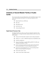
... playback Performs 4:1, 3:1 and 2:1 ADPCM decompression in Sound Blaster mode Control the sampling rate Interprets Sound Blaster compatible MIDI and MPU-401 UART mode commands (Sound Blaster 16 only) Provides communication path between Host and the Advanced Signal Processor (Sound Blaster 16 Advanced Signal Processing only) Provides the Advanced Signal Processor's code downloading (Sound Blaster 16 Advanced Signal Processing only) Provides...
... playback Performs 4:1, 3:1 and 2:1 ADPCM decompression in Sound Blaster mode Control the sampling rate Interprets Sound Blaster compatible MIDI and MPU-401 UART mode commands (Sound Blaster 16 only) Provides communication path between Host and the Advanced Signal Processor (Sound Blaster 16 Advanced Signal Processing only) Provides the Advanced Signal Processor's code downloading (Sound Blaster 16 Advanced Signal Processing only) Provides...
Hardware Programming Guide
Page 16
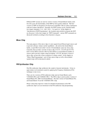
...on the FM synthesizer chip programming. In the later chapter on "DSP Commands", various DSP commands are discussed in earlier versions of Sound Blaster cards, has mixer chip. In the chapter on "Mixer Chip Programming", each of these mixer chips as well as the included... register maps will be discussed in the Sound Blaster family, except SB2.0 and earlier version of Sound Blaster Pro, SB2.0 and Sound Blaster. There are two versions of Sound Blaster Pro, and Sound Blaster 16 use the YAMAHA OPL3 chip. YAMAHA OPL2 and YAMAHA OPL3. The later...
...on the FM synthesizer chip programming. In the later chapter on "DSP Commands", various DSP commands are discussed in earlier versions of Sound Blaster cards, has mixer chip. In the chapter on "Mixer Chip Programming", each of these mixer chips as well as the included... register maps will be discussed in the Sound Blaster family, except SB2.0 and earlier version of Sound Blaster Pro, SB2.0 and Sound Blaster. There are two versions of Sound Blaster Pro, and Sound Blaster 16 use the YAMAHA OPL3 chip. YAMAHA OPL2 and YAMAHA OPL3. The later...
Hardware Programming Guide
Page 17
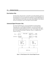
... mode compatible MIDI, FIFOs for providing handshake signals and data transfer between the ISA bus and various components on the Sound Blaster card. The flexibility of algorithms. Below is a technological breakthrough. It also provides real-time signal processing like compression/...playback and recording, and interrupt channel sharing by three different processes (8-bit digitized sound, 16-bit digitized sound and MIDI). On Sound Blaster 16, it can perform high speed mathematical processing on Sound Blaster 16 Advanced Signal Processing cards, is a simplified block diagram of this chip:...
... mode compatible MIDI, FIFOs for providing handshake signals and data transfer between the ISA bus and various components on the Sound Blaster card. The flexibility of algorithms. Below is a technological breakthrough. It also provides real-time signal processing like compression/...playback and recording, and interrupt channel sharing by three different processes (8-bit digitized sound, 16-bit digitized sound and MIDI). On Sound Blaster 16, it can perform high speed mathematical processing on Sound Blaster 16 Advanced Signal Processing cards, is a simplified block diagram of this chip:...
Hardware Programming Guide
Page 19
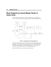
.... Please note the SB2.0 does not contain a mixer chip on board. SPKR CMS Figure 1-2: Block Diagram of the Sound Blaster 2.0 Note that is optional. All Sound Blaster cards that the CMS chip is later than SB2.0 does not have the CMS upgrade socket. JOYSTICK PORT MIDI PORT COMMAND... CHIP CONTROL AD/DA FILTER AGC MIC LINE IN ISA BUS FM SYNTHESIZER POWER AMP. The quality of Sound Blaster cards, we will now present the block diagrams for Sound Blaster Family of Audio Cards After presenting the introduction to synthesize music. 1-6 Hardware Overview Block Diagrams for SB2...
.... Please note the SB2.0 does not contain a mixer chip on board. SPKR CMS Figure 1-2: Block Diagram of the Sound Blaster 2.0 Note that is optional. All Sound Blaster cards that the CMS chip is later than SB2.0 does not have the CMS upgrade socket. JOYSTICK PORT MIDI PORT COMMAND... CHIP CONTROL AD/DA FILTER AGC MIC LINE IN ISA BUS FM SYNTHESIZER POWER AMP. The quality of Sound Blaster cards, we will now present the block diagrams for Sound Blaster Family of Audio Cards After presenting the introduction to synthesize music. 1-6 Hardware Overview Block Diagrams for SB2...
Hardware Programming Guide
Page 20
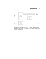
Hardware Overview 1-7 CD IN VOICE IN ISA BUS CT1335 Mixer Chip Power Amp. MUSIC IN SPKR ISA BUS CD Interface TO CD-ROM Drive Figure 1-3: Block Diagram of the Sound Blaster 2.0 CD Interface The SB2CD is the CD-ROM upgrade for software volume control and a power amplifier. It also includes an audio mixer for SB2.0. It provides a CD-ROM interface which the SB2.0 does not have.
Hardware Overview 1-7 CD IN VOICE IN ISA BUS CT1335 Mixer Chip Power Amp. MUSIC IN SPKR ISA BUS CD Interface TO CD-ROM Drive Figure 1-3: Block Diagram of the Sound Blaster 2.0 CD Interface The SB2CD is the CD-ROM upgrade for software volume control and a power amplifier. It also includes an audio mixer for SB2.0. It provides a CD-ROM interface which the SB2.0 does not have.
Hardware Programming Guide
Page 21
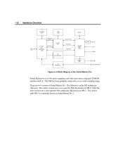
The earlier version uses a two-operator FM chip known as OPL2, while the later version uses a four-operator FM synthesizer chip known as Sound Blaster Pro 2. The different is commonly known as OPL3. The version with stereo mixer chip and CD-ROM interface built in the FM synthesizer chip used. ... MIXER CHIP CD IN MIC IN ISA BUS CONTROL LINE IN FM SYNTHESIZER POWER AMP CD INTERFACE SPKR CD-ROM DRIVE Figure 1-4: Block Diagram of Sound Blaster Pro. There are two versions of the Sound Blaster Pro Sound Blaster Pro is a 8-bit stereo sampling card with OPL3 is in .
The earlier version uses a two-operator FM chip known as OPL2, while the later version uses a four-operator FM synthesizer chip known as Sound Blaster Pro 2. The different is commonly known as OPL3. The version with stereo mixer chip and CD-ROM interface built in the FM synthesizer chip used. ... MIXER CHIP CD IN MIC IN ISA BUS CONTROL LINE IN FM SYNTHESIZER POWER AMP CD INTERFACE SPKR CD-ROM DRIVE Figure 1-4: Block Diagram of Sound Blaster Pro. There are two versions of the Sound Blaster Pro Sound Blaster Pro is a 8-bit stereo sampling card with OPL3 is in .
Hardware Programming Guide
Page 22
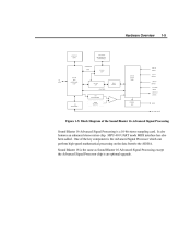
It also features an enhanced stereo mixer chip. Sound Blaster 16 is the same as Sound Blaster 16 Advanced Signal Processing except the Advanced Signal Processor chip is the Advanced Signal Processor which can perform high-speed mathematical processing on the ...data from/to the AD/DA. MPU-401 UART mode MIDI interface has also been added. One of the Sound Blaster 16 Advanced Signal Processing Sound Blaster 16 Advanced Signal Processing is a 16-bit stereo sampling card. Hardware Overview 1-9 JOYSTICK PORT MIDI PORT SB and MPU-401 COMPATIBLE COMMAND/ ...
It also features an enhanced stereo mixer chip. Sound Blaster 16 is the same as Sound Blaster 16 Advanced Signal Processing except the Advanced Signal Processor chip is the Advanced Signal Processor which can perform high-speed mathematical processing on the ...data from/to the AD/DA. MPU-401 UART mode MIDI interface has also been added. One of the Sound Blaster 16 Advanced Signal Processing Sound Blaster 16 Advanced Signal Processing is a 16-bit stereo sampling card. Hardware Overview 1-9 JOYSTICK PORT MIDI PORT SB and MPU-401 COMPATIBLE COMMAND/ ...
Hardware Programming Guide
Page 24
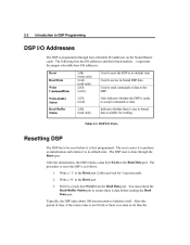
The following lists the I /O addresses. Also indicates whether the DSP is ready to reset the DSP is done through four selectable I/O addresses on the Sound Blaster cards. The DSP reset is as follows: 1. 2. 3. The procedure to accept commands or data. Write a "0" to the DSP. The reset causes it to perform an ...
The following lists the I /O addresses. Also indicates whether the DSP is ready to reset the DSP is done through four selectable I/O addresses on the Sound Blaster cards. The DSP reset is as follows: 1. 2. 3. The procedure to accept commands or data. Write a "0" to the DSP. The reset causes it to perform an ...

