
Hardware Programming Guide
Page 5
...-bit Single-cycle Transfer...3-25 8-bit or 16-bit Auto-initialize Transfer...3-27 Chapter 4 Mixer Chip Programming Programming Sequence...4-2 CT1335 Mixer ...4-4 Features ...4-4 Register Functions ...4-4 CT1345 Mixer ...4-6 Features ...4-6 Register Functions ...4-7 CT1745 Mixer ...4-10 Features ...4-10 Register Functions ...4-11 Chapter 5 MIDI Port I/O Programming SB-MIDI Mode...5-2 I/O Addresses...5-2 Sending MIDI Data...5-3 Reading MIDI Data...5-4 MPU-401...
...-bit Single-cycle Transfer...3-25 8-bit or 16-bit Auto-initialize Transfer...3-27 Chapter 4 Mixer Chip Programming Programming Sequence...4-2 CT1335 Mixer ...4-4 Features ...4-4 Register Functions ...4-4 CT1345 Mixer ...4-6 Features ...4-6 Register Functions ...4-7 CT1745 Mixer ...4-10 Features ...4-10 Register Functions ...4-11 Chapter 5 MIDI Port I/O Programming SB-MIDI Mode...5-2 I/O Addresses...5-2 Sending MIDI Data...5-3 Reading MIDI Data...5-4 MPU-401...
Hardware Programming Guide
Page 15
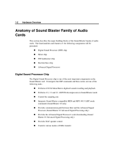
... Processor Digital Sound Processor Chip The Digital Sound Processor chip is one of the most important components on the Sound Blaster card. The functionalities and features of the following tasks Performs 8/16 bit Mono/Stereo digitized sound recording and playback Performs 4:1, 3:1 and 2:1 ADPCM decompression in Sound Blaster mode Control the sampling...
... Processor Digital Sound Processor Chip The Digital Sound Processor chip is one of the most important components on the Sound Blaster card. The functionalities and features of the following tasks Performs 8/16 bit Mono/Stereo digitized sound recording and playback Performs 4:1, 3:1 and 2:1 ADPCM decompression in Sound Blaster mode Control the sampling...
Hardware Programming Guide
Page 16
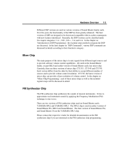
... family, except SB2.0 and earlier version of volume control. The later version of mixer chip, can be downward compatible with its earlier counterparts with new features introduced. Mixer Chip The main purpose of Sound Blaster family cards. Please contact the respective vendor for detailed documentation on the FM synthesizer chip if...
... family, except SB2.0 and earlier version of volume control. The later version of mixer chip, can be downward compatible with its earlier counterparts with new features introduced. Mixer Chip The main purpose of Sound Blaster family cards. Please contact the respective vendor for detailed documentation on the FM synthesizer chip if...
Hardware Programming Guide
Page 18
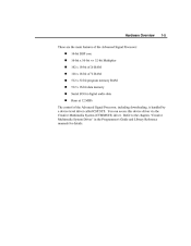
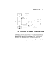
...-bit program memory RAM 512 x 16-bit data memory Serial I/O for details. You can access this device driver via the Creative Multimedia System (CTMMSYS) driver. Hardware Overview 1-5 These are the main features of the Advanced Signal Processor 16-bit DSP core 16-bit x 16-bit => 32-bit Multiplier 192 x 16-bit of...
...-bit program memory RAM 512 x 16-bit data memory Serial I/O for details. You can access this device driver via the Creative Multimedia System (CTMMSYS) driver. Hardware Overview 1-5 These are the main features of the Advanced Signal Processor 16-bit DSP core 16-bit x 16-bit => 32-bit Multiplier 192 x 16-bit of...
Hardware Programming Guide
Page 22
... the key component is the Advanced Signal Processor which can perform high-speed mathematical processing on the data from/to the AD/DA. It also features an enhanced stereo mixer chip. Sound Blaster 16 is the same as Sound Blaster 16 Advanced Signal Processing except the Advanced Signal Processor chip is...
... the key component is the Advanced Signal Processor which can perform high-speed mathematical processing on the data from/to the AD/DA. It also features an enhanced stereo mixer chip. Sound Blaster 16 is the same as Sound Blaster 16 Advanced Signal Processing except the Advanced Signal Processor chip is...
Hardware Programming Guide
Page 59
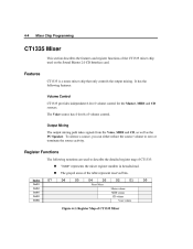
... Three different mixer chips are used on Sound Blaster cards: CT1335, CT1345 and CT1745. It covers the following topics: „ „ „ features of the mixer chips programming sequence of the mixer chips register functions of each mixer chip will first present the sequence to all the mixer... chips. Subsequently, the features and register functions of the mixer chips In the following discussions, we will be presented. CT1335 is used on the Sound Blaster 2.0 ...
... Three different mixer chips are used on Sound Blaster cards: CT1335, CT1345 and CT1745. It covers the following topics: „ „ „ features of the mixer chips programming sequence of the mixer chips register functions of each mixer chip will first present the sequence to all the mixer... chips. Subsequently, the features and register functions of the mixer chips In the following discussions, we will be presented. CT1335 is used on the Sound Blaster 2.0 ...
Hardware Programming Guide
Page 62
The grayed areas of volume control. Register Functions The following features: Volume Control CT1335 provides independent 8-level volume control for the Master, MIDI and CD sources. It has the following notations are used on the Sound ... volume CD volume Voice volume D7 D1 D0 Reset Mixer Figure 4-1: Register Map of CT1335 Mixer 4-4 Mixer Chip Programming CT1335 Mixer This section describes the features and register functions of the CT1335 mixer chip used to zero or terminate the source activity...
The grayed areas of volume control. Register Functions The following features: Volume Control CT1335 provides independent 8-level volume control for the Master, MIDI and CD sources. It has the following notations are used on the Sound ... volume CD volume Voice volume D7 D1 D0 Reset Mixer Figure 4-1: Register Map of CT1335 Mixer 4-4 Mixer Chip Programming CT1335 Mixer This section describes the features and register functions of the CT1335 mixer chip used to zero or terminate the source activity...
Hardware Programming Guide
Page 64
... mixer that controls volume, output mixing, and input source selection as well as the PC Speaker. 4-6 Mixer Chip Programming CT1345 Mixer This section describes the features and register functions of the CT1345 mixer chip used on the CT1345...
... mixer that controls volume, output mixing, and input source selection as well as the PC Speaker. 4-6 Mixer Chip Programming CT1345 Mixer This section describes the features and register functions of the CT1345 mixer chip used on the CT1345...
Hardware Programming Guide
Page 68
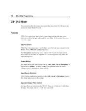
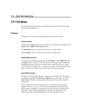
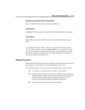
...by toggling some mixer switches to disconnect all four sources from the mixing path. Input Mixing Control In contrast to zero. Features The features of volume control. Volume Control CT1745 provides independent 32-level volume control of the CT1745 mixer chip used on the Sound Blaster... only allows single-source recording, CT1745 supports recording from the output mixing path. One novel feature of volume control. 4-10 Mixer Chip Programming CT1745 Mixer This section describes the features and register functions of both stereo channels for the Master, Voice, MIDI, CD and Line...
...by toggling some mixer switches to disconnect all four sources from the mixing path. Input Mixing Control In contrast to zero. Features The features of volume control. Volume Control CT1745 provides independent 32-level volume control of the CT1745 mixer chip used on the Sound Blaster... only allows single-source recording, CT1745 supports recording from the output mixing path. One novel feature of volume control. 4-10 Mixer Chip Programming CT1745 Mixer This section describes the features and register functions of both stereo channels for the Master, Voice, MIDI, CD and Line...
Hardware Programming Guide
Page 69
... mixer register number in understanding the mixer chip. The following notations are tagged with a "0xRR:D" label on the left /right input/output mixing paths. CT1745 features dynamic filtering. on each of the table represent reserved bits. „ Tone Control Independent 16-level bass and treble control on the logical schematic diagrams...
... mixer register number in understanding the mixer chip. The following notations are tagged with a "0xRR:D" label on the left /right input/output mixing paths. CT1745 features dynamic filtering. on each of the table represent reserved bits. „ Tone Control Independent 16-level bass and treble control on the logical schematic diagrams...
Hardware Programming Guide
Page 139
...2-bit, 3-13 8-bit to 3-bit, 3-13 8-bit to 4-bit, 3-13 Advanced Signal Processor, 1-2, 1-4 block diagram, 1-4 downloading, 1-5 features, 1-5 Auto-initialize mode 16-bit mono/stereo, 3-28 8-bit mono, 3-15, 3-28 8-bit mono ADPCM, 3-15 8-bit mono high-speed...6-1 digitized sound I/O capabilities, 3-8 data format, 3-9 sampling ranges, 3-9 transfer mode, 3-9 digitized sound I/O interrupt handling, 3-12 DMA operation modes, 3-8 features, 1-2 handling interrupt from, 2-4 I/O addresses, 2-2 programming with Time Constant, 3-4 reading from, 2-3 resetting, 2-2 sharing interrupts, 2-5 version, xii writing to...
...2-bit, 3-13 8-bit to 3-bit, 3-13 8-bit to 4-bit, 3-13 Advanced Signal Processor, 1-2, 1-4 block diagram, 1-4 downloading, 1-5 features, 1-5 Auto-initialize mode 16-bit mono/stereo, 3-28 8-bit mono, 3-15, 3-28 8-bit mono ADPCM, 3-15 8-bit mono high-speed...6-1 digitized sound I/O capabilities, 3-8 data format, 3-9 sampling ranges, 3-9 transfer mode, 3-9 digitized sound I/O interrupt handling, 3-12 DMA operation modes, 3-8 features, 1-2 handling interrupt from, 2-4 I/O addresses, 2-2 programming with Time Constant, 3-4 reading from, 2-3 resetting, 2-2 sharing interrupts, 2-5 version, xii writing to...