
Hardware Programming Guide
Page 2
... copyright in which the manual and software are recorded or fixed. By downloading and/or using this agreement and further agrees that : (1) CREATIVE'S BBS/FTP/COMPUSERVE ARE THE ONLY ONLINE SITES WHERE USERS MAY DOWNLOAD ELECTRONIC FILES CONTAINING THE MANUAL AND/OR SOFTWARE, (2) LICENSEE SHALL USE THE MANUAL AND/OR SOFTWARE ONLY FOR THE PURPOSE OF DEVELOPING LICENSEE APPLICATIONS COMPATIBLE WITH CREATIVE'S SOUND BLASTER SERIES OF PRODUCTS, UNLESS...
... copyright in which the manual and software are recorded or fixed. By downloading and/or using this agreement and further agrees that : (1) CREATIVE'S BBS/FTP/COMPUSERVE ARE THE ONLY ONLINE SITES WHERE USERS MAY DOWNLOAD ELECTRONIC FILES CONTAINING THE MANUAL AND/OR SOFTWARE, (2) LICENSEE SHALL USE THE MANUAL AND/OR SOFTWARE ONLY FOR THE PURPOSE OF DEVELOPING LICENSEE APPLICATIONS COMPATIBLE WITH CREATIVE'S SOUND BLASTER SERIES OF PRODUCTS, UNLESS...
Hardware Programming Guide
Page 4
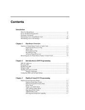
... Know...ix Scope and Manual Organization...ix Document Conventions...x Determining User's Sound Blaster Card ...xii Determining User's Card Settings...xiii Chapter 1 Hardware Overview Anatomy of Sound Blaster Family of Audio Cards...1-2 Digital Sound Processor Chip...1-2 Mixer Chip...1-3 FM Synthesizer Chip...1-3 Bus Interface Chip...1-4 Advanced Signal Processor ...1-4 Block Diagrams for Sound Blaster Family of Audio Cards...1-6 Chapter 2 Introduction to DSP Programming DSP I/O Addresses ...2-2 Resetting DSP...2-2 Reading from DSP...2-3 Writing to DSP ...2-4 Handling Interrupts from...
... Know...ix Scope and Manual Organization...ix Document Conventions...x Determining User's Sound Blaster Card ...xii Determining User's Card Settings...xiii Chapter 1 Hardware Overview Anatomy of Sound Blaster Family of Audio Cards...1-2 Digital Sound Processor Chip...1-2 Mixer Chip...1-3 FM Synthesizer Chip...1-3 Bus Interface Chip...1-4 Advanced Signal Processor ...1-4 Block Diagrams for Sound Blaster Family of Audio Cards...1-6 Chapter 2 Introduction to DSP Programming DSP I/O Addresses ...2-2 Resetting DSP...2-2 Reading from DSP...2-3 Writing to DSP ...2-4 Handling Interrupts from...
Hardware Programming Guide
Page 8
... Digital Sound Processor (DSP), Mixer chip, and MIDI Port. or 16-bit digitized sound. It also controls the selection of various input and output sources. The Digital Sound Processor also supports real-time decompression of ADPCM in mono or stereo, using Single-cycle or Auto-initialize DMA modes. Through this port, MIDI messages can be transmitted to the main Creative-specific Sound Blaster hardware components; Introduction This manual covers the hardware programming information for the following Sound Blaster cards: „ Sound Blaster...
... Digital Sound Processor (DSP), Mixer chip, and MIDI Port. or 16-bit digitized sound. It also controls the selection of various input and output sources. The Digital Sound Processor also supports real-time decompression of ADPCM in mono or stereo, using Single-cycle or Auto-initialize DMA modes. Through this port, MIDI messages can be transmitted to the main Creative-specific Sound Blaster hardware components; Introduction This manual covers the hardware programming information for the following Sound Blaster cards: „ Sound Blaster...
Hardware Programming Guide
Page 9
... code for that range of microprocessors is divided into the following : „ „ „ Digital Sound Processor Mixer Chip MIDI Port Refer to proceed until you need more information on these assumptions. Introduction ix What You Should Know This manual assumes you are familiar with system level programming on the IBM PC. Scope and Manual Organization This manual focuses on the Creative-specific hardware...
... code for that range of microprocessors is divided into the following : „ „ „ Digital Sound Processor Mixer Chip MIDI Port Refer to proceed until you need more information on these assumptions. Introduction ix What You Should Know This manual assumes you are familiar with system level programming on the IBM PC. Scope and Manual Organization This manual focuses on the Creative-specific hardware...
Hardware Programming Guide
Page 10
... 3, "Digitized Sound I/O Programming", describes the programming information for control of the mixer chip. Chapter 5, "MIDI Port I /O. The terms "Single-cycle" and "Auto-initialize" are referred to collectively as Sound Blaster 16. This covers 8-bit and 16-bit, mono and stereo, high-speed and auto-initialize DMA programming. The word "user" does not refer to the person who uses your application. Document Conventions In this manual...
... 3, "Digitized Sound I/O Programming", describes the programming information for control of the mixer chip. Chapter 5, "MIDI Port I /O. The terms "Single-cycle" and "Auto-initialize" are referred to collectively as Sound Blaster 16. This covers 8-bit and 16-bit, mono and stereo, high-speed and auto-initialize DMA programming. The word "user" does not refer to the person who uses your application. Document Conventions In this manual...
Hardware Programming Guide
Page 12
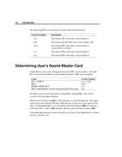
... Advanced Signal Processing Version Number 1.xx to 2.00 2.01+ 3.xx 4.xx The DSP version can read the value from I/O port 388h, two-operator cards will return a value of 06h, and four-operator cards will return a value of SBPRO. The difference is in the discussions: Version Notation 1.xx 2.00 2.01+ 3.xx 4.xx. The table below lists the Sound Blaster cards and their DSP version numbers...
... Advanced Signal Processing Version Number 1.xx to 2.00 2.01+ 3.xx 4.xx The DSP version can read the value from I/O port 388h, two-operator cards will return a value of 06h, and four-operator cards will return a value of SBPRO. The difference is in the discussions: Version Notation 1.xx 2.00 2.01+ 3.xx 4.xx. The table below lists the Sound Blaster cards and their DSP version numbers...
Hardware Programming Guide
Page 13
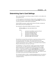
The user will be the same as the card's base I /O port Note that d and h are jumper selectable to configure the Sound Blaster 16 appropriately. However, the hardware also supports transfer 16-bit sound data via 8-bit DMA channel. We encourage developers to adopt, as follows: SET BLASTER=A220 I5 D1 [H5 M220 P330] where: A I D H M P specifies the Sound Blaster card's base I/O port specifies the interrupt request line specifies the 8-bit DMA channel specifies...
The user will be the same as the card's base I /O port Note that d and h are jumper selectable to configure the Sound Blaster 16 appropriately. However, the hardware also supports transfer 16-bit sound data via 8-bit DMA channel. We encourage developers to adopt, as follows: SET BLASTER=A220 I5 D1 [H5 M220 P330] where: A I D H M P specifies the Sound Blaster card's base I/O port specifies the interrupt request line specifies the 8-bit DMA channel specifies...
Hardware Programming Guide
Page 14
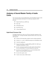
It is meant for developers who intend to do hardware level programming. Chapter 1 Hardware Overview This chapter gives an overview of the hardware architecture of the Sound Blaster family of audio cards. This chapter also covers the anatomy and block diagrams of Sound Blaster family of audio cards. Major building blocks of the Sound Blaster family cards and their functionalities will be discussed.
It is meant for developers who intend to do hardware level programming. Chapter 1 Hardware Overview This chapter gives an overview of the hardware architecture of the Sound Blaster family of audio cards. This chapter also covers the anatomy and block diagrams of Sound Blaster family of audio cards. Major building blocks of the Sound Blaster family cards and their functionalities will be discussed.
Hardware Programming Guide
Page 15
...16 bit Mono/Stereo digitized sound recording and playback Performs 4:1, 3:1 and 2:1 ADPCM decompression in Sound Blaster mode Control the sampling rate Interprets Sound Blaster compatible MIDI and MPU-401 UART mode commands (Sound Blaster 16 only) Provides communication path between Host and the Advanced Signal Processor (Sound Blaster 16 Advanced Signal Processing only) Provides the Advanced Signal Processor's code downloading (Sound Blaster 16 Advanced Signal Processing only) Provides DAC speaker control Controls various modes of DMA transfer 1-2 Hardware Overview Anatomy of Sound Blaster...
...16 bit Mono/Stereo digitized sound recording and playback Performs 4:1, 3:1 and 2:1 ADPCM decompression in Sound Blaster mode Control the sampling rate Interprets Sound Blaster compatible MIDI and MPU-401 UART mode commands (Sound Blaster 16 only) Provides communication path between Host and the Advanced Signal Processor (Sound Blaster 16 Advanced Signal Processing only) Provides the Advanced Signal Processor's code downloading (Sound Blaster 16 Advanced Signal Processing only) Provides DAC speaker control Controls various modes of DMA transfer 1-2 Hardware Overview Anatomy of Sound Blaster...
Hardware Programming Guide
Page 16
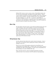
.... The OPL2 chip is to mix signals from the other by applying the Frequency Modulation (FM) technique to provide volume control resolution. The later versions of Sound Blaster Pro, SB2.0 and Sound Blaster. It tries to program the DSP are three versions of Sound Blaster family cards. There are two versions of FM synthesizer chips used on various versions of mixer chip: CT1335 , CT1345 and CT1745...
.... The OPL2 chip is to mix signals from the other by applying the Frequency Modulation (FM) technique to provide volume control resolution. The later versions of Sound Blaster Pro, SB2.0 and Sound Blaster. It tries to program the DSP are three versions of Sound Blaster family cards. There are two versions of FM synthesizer chips used on various versions of mixer chip: CT1335 , CT1345 and CT1745...
Hardware Programming Guide
Page 17
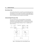
... on Sound Blaster 16 Advanced Signal Processing cards, is a technological breakthrough. It also provides real-time signal processing like compression/decompression of the Advanced Signal Processor Advanced Signal Processor Chip The Advanced Signal Processor, used on digitized sound data. 1-4 Hardware Overview Bus Interface Chip The Bus Interface Chip (CT1336) is responsible for digital audio playback and recording, and interrupt channel sharing by three different processes (8-bit digitized sound, 16-bit digitized sound and MIDI).
... on Sound Blaster 16 Advanced Signal Processing cards, is a technological breakthrough. It also provides real-time signal processing like compression/decompression of the Advanced Signal Processor Advanced Signal Processor Chip The Advanced Signal Processor, used on digitized sound data. 1-4 Hardware Overview Bus Interface Chip The Bus Interface Chip (CT1336) is responsible for digital audio playback and recording, and interrupt channel sharing by three different processes (8-bit digitized sound, 16-bit digitized sound and MIDI).
Hardware Programming Guide
Page 19
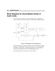
... note the SB2.0 does not contain a mixer chip on board. SPKR CMS Figure 1-2: Block Diagram of Sound Blaster cards, we will now present the block diagrams for Sound Blaster Family of Audio Cards After presenting the introduction to synthesize music. JOYSTICK PORT MIDI PORT COMMAND/ DATA CT1351 DSP CT1336 BUS INTERFACE CHIP CONTROL AD/DA FILTER AGC MIC LINE IN ISA BUS FM SYNTHESIZER POWER AMP. All Sound Blaster cards that is optional.
... note the SB2.0 does not contain a mixer chip on board. SPKR CMS Figure 1-2: Block Diagram of Sound Blaster cards, we will now present the block diagrams for Sound Blaster Family of Audio Cards After presenting the introduction to synthesize music. JOYSTICK PORT MIDI PORT COMMAND/ DATA CT1351 DSP CT1336 BUS INTERFACE CHIP CONTROL AD/DA FILTER AGC MIC LINE IN ISA BUS FM SYNTHESIZER POWER AMP. All Sound Blaster cards that is optional.
Hardware Programming Guide
Page 20
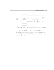
MUSIC IN SPKR ISA BUS CD Interface TO CD-ROM Drive Figure 1-3: Block Diagram of the Sound Blaster 2.0 CD Interface The SB2CD is the CD-ROM upgrade for software volume control and a power amplifier. It provides a CD-ROM interface which the SB2.0 does not have. It also includes an audio mixer for SB2.0. Hardware Overview 1-7 CD IN VOICE IN ISA BUS CT1335 Mixer Chip Power Amp.
MUSIC IN SPKR ISA BUS CD Interface TO CD-ROM Drive Figure 1-3: Block Diagram of the Sound Blaster 2.0 CD Interface The SB2CD is the CD-ROM upgrade for software volume control and a power amplifier. It provides a CD-ROM interface which the SB2.0 does not have. It also includes an audio mixer for SB2.0. Hardware Overview 1-7 CD IN VOICE IN ISA BUS CT1335 Mixer Chip Power Amp.
Hardware Programming Guide
Page 24
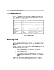
... programmed through the Reset port. The DSP reset is no data at the Read Data port. You must check the Read-Buffer Status port to the Reset port. Also indicates whether the DSP is ready to DSP Programming DSP I /O addresses on the Sound Blaster cards. 2-2 Introduction to accept commands or data. The following lists the I /O addresses. Used to its default state. Indicates whether...
... programmed through the Reset port. The DSP reset is no data at the Read Data port. You must check the Read-Buffer Status port to the Reset port. Also indicates whether the DSP is ready to DSP Programming DSP I /O addresses on the Sound Blaster cards. 2-2 Introduction to accept commands or data. The following lists the I /O addresses. Used to its default state. Indicates whether...
Hardware Programming Guide
Page 25
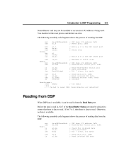
Introduction to DSP Programming 2-3 Sound Blaster card may not be installed or an incorrect I/O address is available, it can be checked to ensure that there is read in cmp je dx,wSBCBaseAddx dl,6 al,1 dx,al ... process and declare an error. If bit-7 is 1, then there is available. Otherwise, no data is data to reset DSP: Sound Blaster not detected! Read Data port, 2xAh ; The following assembly code fragment shows the process of resetting the DSP: mov add mov out sub Delay: dec jnz out sub Empty: mov add in or jns sub in , bit-7 of 65536 tries ; SBC...
Introduction to DSP Programming 2-3 Sound Blaster card may not be installed or an incorrect I/O address is available, it can be checked to ensure that there is read in cmp je dx,wSBCBaseAddx dl,6 al,1 dx,al ... process and declare an error. If bit-7 is 1, then there is available. Otherwise, no data is data to reset DSP: Sound Blaster not detected! Read Data port, 2xAh ; The following assembly code fragment shows the process of resetting the DSP: mov add mov out sub Delay: dec jnz out sub Empty: mov add in or jns sub in , bit-7 of 65536 tries ; SBC...
Hardware Programming Guide
Page 33
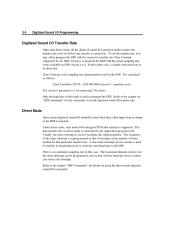
... output to the DSP. 3-4 Digitized Sound I/O Programming Digitized Sound I/O Transfer Rate Other than direct mode, all DSP versions), or program the DSP with the actual sampling rate (only available on using the direct mode digitized sound I/O commands. Under direct mode, only mono 8-bit unsigned PCM data transfer is used to read the in this implementation. Usually, the timer interrupt is carried out. To set before any transfer is used when direct data input...
... output to the DSP. 3-4 Digitized Sound I/O Programming Digitized Sound I/O Transfer Rate Other than direct mode, all DSP versions), or program the DSP with the actual sampling rate (only available on using the direct mode digitized sound I/O commands. Under direct mode, only mono 8-bit unsigned PCM data transfer is used to read the in this implementation. Usually, the timer interrupt is carried out. To set before any transfer is used when direct data input...
Hardware Programming Guide
Page 59
... is used on the Sound Blaster 2.0 CD Interface card, CT1345 is used on the Sound Blaster Pro and CT1745 is used on the Sound Blaster 16. It covers the following discussions, we will be presented. This sequence applies to access the mixer chip. Subsequently, the features and register functions of the mixer chips In the following topics: „ „ „ features of the mixer...
... is used on the Sound Blaster 2.0 CD Interface card, CT1345 is used on the Sound Blaster Pro and CT1745 is used on the Sound Blaster 16. It covers the following discussions, we will be presented. This sequence applies to access the mixer chip. Subsequently, the features and register functions of the mixer chips In the following topics: „ „ „ features of the mixer...
Hardware Programming Guide
Page 76
... all the Sound Blaster cards. MPU-401 UART mode is possible to DSP Programming" on Sound Blaster 16 because it has its own independent I/O ports and interrupt status bit which means that you have digitized sound and MIDI I/O running together. You can use the MPU-401 mode on these subjects. Refer to the chapter "Introduction to have knowledge of the MIDI interfaces. Chapter 5 MIDI Port I /O ports and interrupt...
... all the Sound Blaster cards. MPU-401 UART mode is possible to DSP Programming" on Sound Blaster 16 because it has its own independent I/O ports and interrupt status bit which means that you have digitized sound and MIDI I/O running together. You can use the MPU-401 mode on these subjects. Refer to the chapter "Introduction to have knowledge of the MIDI interfaces. Chapter 5 MIDI Port I /O ports and interrupt...
Hardware Programming Guide
Page 115
In the following discussion, x is used by Sound Blaster cards. The factory default base I/O address setting for all Sound Blaster cards is identical to denote the selected base I /O addresses from 200h to avoid conflicts with other add-on Sound Blaster cards is 220 Hex. The joystick port on cards. Thus, it uses I /O address. Appendix A Sound Blaster I/O Address Maps This appendix lists the I /O addresses are selectable to 207h. The base I /O addresses used to the standard PC Game Control Adapter (or game I/O port).
In the following discussion, x is used by Sound Blaster cards. The factory default base I/O address setting for all Sound Blaster cards is identical to denote the selected base I /O addresses from 200h to avoid conflicts with other add-on Sound Blaster cards is 220 Hex. The joystick port on cards. Thus, it uses I /O address. Appendix A Sound Blaster I/O Address Maps This appendix lists the I /O addresses are selectable to 207h. The base I /O addresses used to the standard PC Game Control Adapter (or game I/O port).
Hardware Programming Guide
Page 138
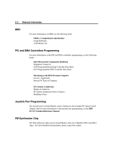
... IBM PC/AT Technical Reference Manual. FM Synthesizer Chip The FM synthesizer chips used on Sound Blaster cards are YAMAHA OPL2 and OPL3 chips. For more detailed documentation, please contact the vendor. Sams & Company ISA System Architecture Shanley & Anderson PC System Architecture Series Volume 1 MindShare Press. C-2 Relevant Information MIDI For more information on MIDI, see the following books: Intel...
... IBM PC/AT Technical Reference Manual. FM Synthesizer Chip The FM synthesizer chips used on Sound Blaster cards are YAMAHA OPL2 and OPL3 chips. For more detailed documentation, please contact the vendor. Sams & Company ISA System Architecture Shanley & Anderson PC System Architecture Series Volume 1 MindShare Press. C-2 Relevant Information MIDI For more information on MIDI, see the following books: Intel...

