End User License Agreement
Page 2
... the basis for commercial timesharing or bureau use the Software Product for your license is effective unless terminated or rejected. You shall not remove any term or condition of the Software Product, your upgrade eligibility. 3. TERM. CONSENT TO USE OF DATA. Third Party. ADDITIONAL ...Product provided by law, including but not limited to do so is mandated under applicable law notwithstanding this EULA. 7. In case of a hard disk drive-based solution, an external media-based recovery solution (e.g. TRANSFER. You may not rent, lease or lend the Software Product or use ....
... the basis for commercial timesharing or bureau use the Software Product for your license is effective unless terminated or rejected. You shall not remove any term or condition of the Software Product, your upgrade eligibility. 3. TERM. CONSENT TO USE OF DATA. Third Party. ADDITIONAL ...Product provided by law, including but not limited to do so is mandated under applicable law notwithstanding this EULA. 7. In case of a hard disk drive-based solution, an external media-based recovery solution (e.g. TRANSFER. You may not rent, lease or lend the Software Product or use ....
Evo Notebook N600c Software Overview
Page 12
... that provides easy access to unlock a protected drive for the Armada, 2nd ed., February 1998. 15KR-0901A-WWEN Compaq Support Windows 2000 Software CD ! In addition to the Compaq white paper, DriveLock Hard Drive Protection for which provide customers with DriveLock remain protected even if removed from the notebook. Compaq ! Evo N600c computers feature the ATI Mobility Radeon (M6...
... that provides easy access to unlock a protected drive for the Armada, 2nd ed., February 1998. 15KR-0901A-WWEN Compaq Support Windows 2000 Software CD ! In addition to the Compaq white paper, DriveLock Hard Drive Protection for which provide customers with DriveLock remain protected even if removed from the notebook. Compaq ! Evo N600c computers feature the ATI Mobility Radeon (M6...
Hard Drive White Paper
Page 3
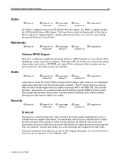
... automatically runs. 3. The notebook must first be applied to all currently shipping notebooks. The short test runs. The F10 Setup Hard Drive Self-Test enhancement is available as one test option. HP recommends the latest system BIOS upgrade be undocked or removed from a docking device or...allow the user to connect to the Evo N400 and Evo N600 series. Note 2: The Microsoft Windows 2000 and Windows XP operating systems provide a feature called Lid Switch Standby. Notebook F10 Setup Hard Drive Self-Test HP has enhanced the Hard Drive Self-Test routine which is operating ...
... automatically runs. 3. The notebook must first be applied to all currently shipping notebooks. The short test runs. The F10 Setup Hard Drive Self-Test enhancement is available as one test option. HP recommends the latest system BIOS upgrade be undocked or removed from a docking device or...allow the user to connect to the Evo N400 and Evo N600 series. Note 2: The Microsoft Windows 2000 and Windows XP operating systems provide a feature called Lid Switch Standby. Notebook F10 Setup Hard Drive Self-Test HP has enhanced the Hard Drive Self-Test routine which is operating ...
Hard Drive White Paper
Page 4
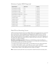
... hard drive. Note: Customers should always be replaced after they are removed or when they are missing, they can be correctly installed at all times. Minimum System BIOS Required Notebook Platform HP Compaq Business nc8000 HP Compaq Business nw8000 HP Compaq Business nc6000 HP Compaq Business nc4000 Series HP Compaq Business nx9000 Series HP Compaq Business nx5000 Compaq Evo N620c Compaq Evo N610c/v Compaq Evo N600c Compaq Evo...
... hard drive. Note: Customers should always be replaced after they are removed or when they are missing, they can be correctly installed at all times. Minimum System BIOS Required Notebook Platform HP Compaq Business nc8000 HP Compaq Business nw8000 HP Compaq Business nc6000 HP Compaq Business nc4000 Series HP Compaq Business nx9000 Series HP Compaq Business nx5000 Compaq Evo N620c Compaq Evo N610c/v Compaq Evo N600c Compaq Evo...
Hard Drive White Paper
Page 5
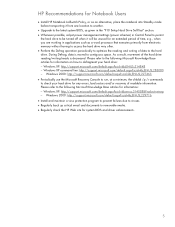
.... HP Recommendations for Notebook Users • Install HP Notebook LidSwitch Policy, or as an alternative, place the notebook into Standby mode before transporting it from one location to another. • Upgrade to the latest system BIOS, as given in the "F10 Setup Hard Drive Self-Test" section....Perform the Defrag operation periodically to optimize the reading and writing of readable information. As a result, movement of the hard drive reading/writing heads is moved to removable media. • Regularly check the HP Web site for system BIOS and driver enhancements. 5 Windows XP: http://...
.... HP Recommendations for Notebook Users • Install HP Notebook LidSwitch Policy, or as an alternative, place the notebook into Standby mode before transporting it from one location to another. • Upgrade to the latest system BIOS, as given in the "F10 Setup Hard Drive Self-Test" section....Perform the Defrag operation periodically to optimize the reading and writing of readable information. As a result, movement of the hard drive reading/writing heads is moved to removable media. • Regularly check the HP Web site for system BIOS and driver enhancements. 5 Windows XP: http://...
Maintenance and Service Guide
Page 51
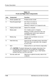
Off: Power is charging. Battery light On: A battery pack is turned off. The hard drive is the only available power source has reached a low-battery condition. Product Description Table 1-6 Front and Right Side Components Item 1 2 3 4 5 6 7 8 Component Function Stereo speakers (2) Produce .... Ä CAUTION: To prevent damage, the computer shuts down if an overheating condition occurs. Battery bay Accepts an 8-cell lithium ion (Li ion) battery pack. Hard drive bay Supports the removable primary hard drive.
Off: Power is charging. Battery light On: A battery pack is turned off. The hard drive is the only available power source has reached a low-battery condition. Product Description Table 1-6 Front and Right Side Components Item 1 2 3 4 5 6 7 8 Component Function Stereo speakers (2) Produce .... Ä CAUTION: To prevent damage, the computer shuts down if an overheating condition occurs. Battery bay Accepts an 8-cell lithium ion (Li ion) battery pack. Hard drive bay Supports the removable primary hard drive.

Maintenance and Service Guide
Page 60
...1-55 Exhaust air is designed to identify replacement parts, and Chapter 5, "Removal and Replacement Procedures," for ventilation. The system board provides the following device connections: ■ Memory expansion board ■ Hard drive ■ Display ■ Keyboard/TouchPad or pointing stick ■ Audio... ■ Intel Mobile Pentium 4 processors with SpeedStep technology ■ Fan ■ PC Card ■ Modem or modem/NIC The computer ...
...1-55 Exhaust air is designed to identify replacement parts, and Chapter 5, "Removal and Replacement Procedures," for ventilation. The system board provides the following device connections: ■ Memory expansion board ■ Hard drive ■ Display ■ Keyboard/TouchPad or pointing stick ■ Audio... ■ Intel Mobile Pentium 4 processors with SpeedStep technology ■ Fan ■ PC Card ■ Modem or modem/NIC The computer ...

Maintenance and Service Guide
Page 81
... OS Loading from Diskette Drive. N CD or diskette in drive? Y N Go to Section 2.12, No OS Loading from hard drive? Load OS using Restore CD (if applicable). Done Remove diskette and reboot. Replace system board. Y Boot from Hard Drive, Part 3. Hard drive accessible? Y Go to Section 2.13, No OS Loading from Hard Drive, Part 3. Done N Hard drive partitioned? Y Format hard drive and bring to bootable...
... OS Loading from Diskette Drive. N CD or diskette in drive? Y N Go to Section 2.12, No OS Loading from hard drive? Load OS using Restore CD (if applicable). Done Remove diskette and reboot. Replace system board. Y Boot from Hard Drive, Part 3. Hard drive accessible? Y Go to Section 2.13, No OS Loading from Hard Drive, Part 3. Done N Hard drive partitioned? Y Format hard drive and bring to bootable...
Maintenance and Service Guide
Page 114
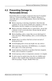
... the drive in the drive. Ensure that the optical drive tray is not in a bubble pack mailer or other suitable form of shock-proof foam. ■ Avoid dropping drives from any height onto any surface. ■ After removing a hard drive, CD-ROM drive, or a diskette drive, place it down the computer. Removal and Replacement Preliminaries 4.3 Preventing Damage to Removable Drives Removable drives are fragile...
... the drive in the drive. Ensure that the optical drive tray is not in a bubble pack mailer or other suitable form of shock-proof foam. ■ Avoid dropping drives from any height onto any surface. ■ After removing a hard drive, CD-ROM drive, or a diskette drive, place it down the computer. Removal and Replacement Preliminaries 4.3 Preventing Damage to Removable Drives Removable drives are fragile...

Maintenance and Service Guide
Page 122
... Speaker assembly 5.13 Display release assembly 5.14 TouchPad 5.15 Fan 5.16 Processor 5.17 Disk cell RTC battery 5.18 System board 5.19 Modem cable # of Screws Removed 0 1 to remove hard drive 2 to separate hard drive bezel from hard drive 0 1 loosened 1 loosened 2 2 2 to remove keyboard shield 4 16 0 2 4 4 loosened 0 0 5 0 Maintenance and Service Guide 5-3
... Speaker assembly 5.13 Display release assembly 5.14 TouchPad 5.15 Fan 5.16 Processor 5.17 Disk cell RTC battery 5.18 System board 5.19 Modem cable # of Screws Removed 0 1 to remove hard drive 2 to separate hard drive bezel from hard drive 0 1 loosened 1 loosened 2 2 2 to remove keyboard shield 4 16 0 2 4 4 loosened 0 0 5 0 Maintenance and Service Guide 5-3
Maintenance and Service Guide
Page 126
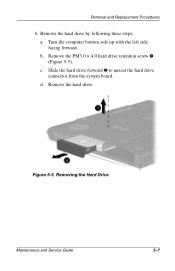
b. Slide the hard drive forward 2 to unseat the hard drive connector from the system board. d. Removal and Replacement Procedures 6. Turn the computer bottom side up with the left side facing forward. c. Remove the PM3.0 × 4.0 hard drive retention screw 1 (Figure 5-5). Figure 5-5. Removing the Hard Drive Maintenance and Service Guide 5-7 Remove the hard drive. Remove the hard drive by following these steps: a.
b. Slide the hard drive forward 2 to unseat the hard drive connector from the system board. d. Removal and Replacement Procedures 6. Turn the computer bottom side up with the left side facing forward. c. Remove the PM3.0 × 4.0 hard drive retention screw 1 (Figure 5-5). Figure 5-5. Removing the Hard Drive Maintenance and Service Guide 5-7 Remove the hard drive. Remove the hard drive by following these steps: a.

Maintenance and Service Guide
Page 127
Removing the Hard Drive Bezel Hard Drive Bezel Spare Part Number Information Hard drive bezel with silver finish for use with Presario 2800 models Hard drive bezel with carbon finish for use with Evo Notebook N800c, N800v, and N800w models 286874-001 286875-001 Reverse the above procedure to separate it from the hard drive 2. Slide the hard drive bezel forward to install the hard drive and hard drive bezel. 5-8 Maintenance...
Removing the Hard Drive Bezel Hard Drive Bezel Spare Part Number Information Hard drive bezel with silver finish for use with Presario 2800 models Hard drive bezel with carbon finish for use with Evo Notebook N800c, N800v, and N800w models 286874-001 286875-001 Reverse the above procedure to separate it from the hard drive 2. Slide the hard drive bezel forward to install the hard drive and hard drive bezel. 5-8 Maintenance...
Maintenance and Service Guide
Page 146
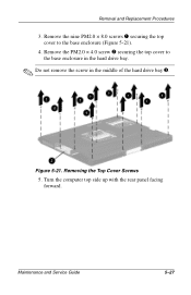
Removing the Top Cover Screws 5. Remove the nine PM2.0 × 8.0 screws 1 securing the top cover to the base enclosure in the hard drive bay. ✎ Do not remove the screw in the middle of the hard drive bay 3. Turn the computer top side up with the rear panel facing forward. Remove the PM2.0 × 4.0 screw 2 securing the top cover to the base enclosure (Figure 5-21). 4. Figure 5-21. Maintenance and Service Guide 5-27 Removal and Replacement Procedures 3.
Removing the Top Cover Screws 5. Remove the nine PM2.0 × 8.0 screws 1 securing the top cover to the base enclosure in the hard drive bay. ✎ Do not remove the screw in the middle of the hard drive bay 3. Turn the computer top side up with the rear panel facing forward. Remove the PM2.0 × 4.0 screw 2 securing the top cover to the base enclosure (Figure 5-21). 4. Figure 5-21. Maintenance and Service Guide 5-27 Removal and Replacement Procedures 3.

Maintenance and Service Guide
Page 218
... 1-50 front components 1-45 function keys 1-50 G grounding equipment and methods 4-6 H hard drive OS loading problems 2-20 removal 5-7, 5-8 spare part numbers 3-9, 3-19 specifications 6-7 hard drive bay 1-46, 1-54 hard drive bezel removal 5-8 spare part numbers 3-9 hard drive retention screw 1-54 headphone jack location 1-48 pin assignments A-6 hinge covers illustrated 3-16 removal 5-25 I I/O address specifications 6-16 illustrated parts catalog 3-1 infrared port 1-47...
... 1-50 front components 1-45 function keys 1-50 G grounding equipment and methods 4-6 H hard drive OS loading problems 2-20 removal 5-7, 5-8 spare part numbers 3-9, 3-19 specifications 6-7 hard drive bay 1-46, 1-54 hard drive bezel removal 5-8 spare part numbers 3-9 hard drive retention screw 1-54 headphone jack location 1-48 pin assignments A-6 hinge covers illustrated 3-16 removal 5-25 I I/O address specifications 6-16 illustrated parts catalog 3-1 infrared port 1-47...

Maintenance and Service Guide
Page 220
... bezel illustrated 3-16 removal 5-48 PC Card eject button 1-48 PC Card slot 1-48 PC Card slot space saver 3-16 plastic parts 4-2 pointing device, troubleshooting 2-29 port replicators, spare part numbers 3-20 power button... 1-54, 3-1, 5-2 service considerations 4-2 speaker assembly removal 5-31 spare part number 3-11 speaker jack location 1-48 pin assignments A-6 speakers 1-46 specifications AC adapter 6-13 battery 6-13 CD-ROM drive 6-10 CD-RW drive 6-12 computer 6-1 diskette drive 6-9 display 6-3, 6-4, 6-5, 6-6 DMA 6-14 DVD-ROM drive 6-11 hard drive 6-7 Maintenance and Service Guide Index-5
... bezel illustrated 3-16 removal 5-48 PC Card eject button 1-48 PC Card slot 1-48 PC Card slot space saver 3-16 plastic parts 4-2 pointing device, troubleshooting 2-29 port replicators, spare part numbers 3-20 power button... 1-54, 3-1, 5-2 service considerations 4-2 speaker assembly removal 5-31 spare part number 3-11 speaker jack location 1-48 pin assignments A-6 speakers 1-46 specifications AC adapter 6-13 battery 6-13 CD-ROM drive 6-10 CD-RW drive 6-12 computer 6-1 diskette drive 6-9 display 6-3, 6-4, 6-5, 6-6 DMA 6-14 DVD-ROM drive 6-11 hard drive 6-7 Maintenance and Service Guide Index-5


