
Hardware Installation Guide
Page 5
... Performance 4-4 Speed, Duplex, and Autonegotiation 4-4 Autonegotiation and NIC Cards 4-5 Cabling Distance 4-5 Clearing the Switch IP Address and Configuration 4-5 Locating the Switch Serial Number 4-6 Technical Specifications A-1 Connector and Cable Specifications B-1 Connector Specifications B-1 10/100/1000 Ports B-1 Connecting to 1000BASE-T Devices B-2 SFP Module Ports B-3 Dual-Purpose Ports B-3 Catalyst 2960 Switch Hardware Installation Guide v Contents 4 C H A P T E R A A P P E N D I X B A P P E N D I X OL-7075...
... Performance 4-4 Speed, Duplex, and Autonegotiation 4-4 Autonegotiation and NIC Cards 4-5 Cabling Distance 4-5 Clearing the Switch IP Address and Configuration 4-5 Locating the Switch Serial Number 4-6 Technical Specifications A-1 Connector and Cable Specifications B-1 Connector Specifications B-1 10/100/1000 Ports B-1 Connecting to 1000BASE-T Devices B-2 SFP Module Ports B-3 Dual-Purpose Ports B-3 Catalyst 2960 Switch Hardware Installation Guide v Contents 4 C H A P T E R A A P P E N D I X B A P P E N D I X OL-7075...

Hardware Installation Guide
Page 37
... RPS to front and rear panels meets these conditions: - Tools and Equipment You need to insert an inline optical attenuator in Appendix A, "Technical Specifications." • Clearance to the switch, put the RPS in a closed or multirack assembly, the temperature around the unit does not exceed 113...°F (45°C). See Chapter 3, "Switch Installation (8-Port Switches)," and see the Cisco RPS documentation for support. The rear-panel power connector is within the ranges listed in the link to ports is away from other end...
... RPS to front and rear panels meets these conditions: - Tools and Equipment You need to insert an inline optical attenuator in Appendix A, "Technical Specifications." • Clearance to the switch, put the RPS in a closed or multirack assembly, the temperature around the unit does not exceed 113...°F (45°C). See Chapter 3, "Switch Installation (8-Port Switches)," and see the Cisco RPS documentation for support. The rear-panel power connector is within the ranges listed in the link to ports is away from other end...

Hardware Installation Guide
Page 38
... describes these installation procedures: • Rack-Mounting, page 2-6 • Wall-Mounting, page 2-11 • Table- The following Cisco RPS model to the top with stabilizing devices, install the stabilizers before mounting or servicing the unit in the rack. • When... 2 Switch Installation (24- and 48-Port Switches) Warning Attach only the following guidelines are usually fatal. Call Cisco technical support representative if your specific switch; Installing the Switch This section applies to those switches, see Chapter 3, "Switch Installation (8-Port Switches)." and 48...
... describes these installation procedures: • Rack-Mounting, page 2-6 • Wall-Mounting, page 2-11 • Table- The following Cisco RPS model to the top with stabilizing devices, install the stabilizers before mounting or servicing the unit in the rack. • When... 2 Switch Installation (24- and 48-Port Switches) Warning Attach only the following guidelines are usually fatal. Call Cisco technical support representative if your specific switch; Installing the Switch This section applies to those switches, see Chapter 3, "Switch Installation (8-Port Switches)." and 48...

Hardware Installation Guide
Page 57
...strongly recommend that you allow at its maximum temperature 113°F (45°C) and is in an environment that suitable grounding is specific to all national laws and regulations. Never defeat the ground conductor or operate the equipment in a multirack assembly, the temperature around it...the building where the equipment is installed, the following ports must be hot to the touch if the switch is installed in Appendix A, "Technical Specifications." • Airflow around the switch must not exceed 85 percent. • Altitude at the installation site must always be grounded. Do ...
...strongly recommend that you allow at its maximum temperature 113°F (45°C) and is in an environment that suitable grounding is specific to all national laws and regulations. Never defeat the ground conductor or operate the equipment in a multirack assembly, the temperature around it...the building where the equipment is installed, the following ports must be hot to the touch if the switch is installed in Appendix A, "Technical Specifications." • Airflow around the switch must not exceed 85 percent. • Altitude at the installation site must always be grounded. Do ...

Hardware Installation Guide
Page 59
...RCKMNT-19-CMPCT=. and 48-Port Switches)." or Shelf-Mounting (without Mounting Screws), page 3-6 • Desk- The kit part number is specific to -DB-25 female DTE adapter. Tools and Equipment You need to provide an RJ-45-to the Catalyst 2960 8-port switches. LEDs... connect the other Catalyst 2960 switches, see Chapter 2, "Switch Installation (24- As the switch powers on Cisco.com describes the box contents. Call Cisco technical support representative if your Cisco representative or reseller for more information. You can power the Catalyst 2960PD-8TT-L switch through a 10/100/1000...
...RCKMNT-19-CMPCT=. and 48-Port Switches)." or Shelf-Mounting (without Mounting Screws), page 3-6 • Desk- The kit part number is specific to -DB-25 female DTE adapter. Tools and Equipment You need to provide an RJ-45-to the Catalyst 2960 8-port switches. LEDs... connect the other Catalyst 2960 switches, see Chapter 2, "Switch Installation (24- As the switch powers on Cisco.com describes the box contents. Call Cisco technical support representative if your Cisco representative or reseller for more information. You can power the Catalyst 2960PD-8TT-L switch through a 10/100/1000...
Hardware Installation Guide
Page 81
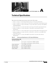
A A P P E N D I X Technical Specifications These tables list the technical specifications for the Catalyst 2960 switches: • Table A-1 on page A-1, Environmental Specifications for All Catalyst 2960 Switches • Table A-2 on page A-2, Catalyst 2960-24-S, 2960-24TC-S, and 2960-48TC-S Switch Specifications • Table A-3 on page A-2, Catalyst 2960-24PC-L, Catalyst 2960-24LT-L, and Catalyst 2960-48PST-L Switch Specifications • Table A-4 on page...
A A P P E N D I X Technical Specifications These tables list the technical specifications for the Catalyst 2960 switches: • Table A-1 on page A-1, Environmental Specifications for All Catalyst 2960 Switches • Table A-2 on page A-2, Catalyst 2960-24-S, 2960-24TC-S, and 2960-48TC-S Switch Specifications • Table A-3 on page A-2, Catalyst 2960-24PC-L, Catalyst 2960-24LT-L, and Catalyst 2960-48PST-L Switch Specifications • Table A-4 on page...
Hardware Installation Guide
Page 82
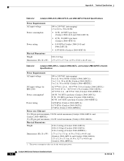
Catalyst 2960 Switch Hardware Installation Guide A-2 OL-7075-09 Appendix A Technical Specifications Table A-2 Catalyst 2960-24-S, 2960-24TC-S, and 2960-48TC-S Switch Specifications Power Requirements AC input voltage Power consumption Power rating Physical Dimensions Weight Dimensions (H x D x W) 100 to 240 VAC (... x 17.5 in . (4.39 x 23.62 x 44.45 cm) Table A-3 Catalyst 2960-24PC-L, Catalyst 2960-24LT-L, and Catalyst 2960-48PST-L Switch Specifications Power Requirements AC input voltage 100 to 240 VAC (autoranging) 8 to 4 A, 50 to 60 Hz (Catalyst 2960-24PC-L) 3 to 1.5 A, 50 to...
Catalyst 2960 Switch Hardware Installation Guide A-2 OL-7075-09 Appendix A Technical Specifications Table A-2 Catalyst 2960-24-S, 2960-24TC-S, and 2960-48TC-S Switch Specifications Power Requirements AC input voltage Power consumption Power rating Physical Dimensions Weight Dimensions (H x D x W) 100 to 240 VAC (... x 17.5 in . (4.39 x 23.62 x 44.45 cm) Table A-3 Catalyst 2960-24PC-L, Catalyst 2960-24LT-L, and Catalyst 2960-48PST-L Switch Specifications Power Requirements AC input voltage 100 to 240 VAC (autoranging) 8 to 4 A, 50 to 60 Hz (Catalyst 2960-24PC-L) 3 to 1.5 A, 50 to...

Hardware Installation Guide
Page 83
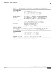
Appendix A Technical Specifications OL-7075-09 Table A-4 Catalyst 2960-24TC-L and Catalyst 2960-24TT-L Switch Specifications Power Requirements AC input voltage DC input voltage for RPS 2300 DC input voltage for RPS 675 Power consumption Power rating Physical Dimensions Weight Dimensions (H x D x W)...-L) 140 W, 477 BTUs per hour (Catalyst 2960G-48TC-L) 0.075 KVA (Catalyst 2960G-24TC-L 0.14 KVA (Catalyst 2960G-48TC-L 10 lb (4.54 kg) (Catalyst 2960G-24T-L) 12 lb (5.44 kg) (Catalyst 2960G-48TC-L 1.73 x 12.9 x 17.5 in. (4.39 x 32.76 x 44.45 cm) Catalyst 2960 Switch Hardware Installation Guide...
Appendix A Technical Specifications OL-7075-09 Table A-4 Catalyst 2960-24TC-L and Catalyst 2960-24TT-L Switch Specifications Power Requirements AC input voltage DC input voltage for RPS 2300 DC input voltage for RPS 675 Power consumption Power rating Physical Dimensions Weight Dimensions (H x D x W)...-L) 140 W, 477 BTUs per hour (Catalyst 2960G-48TC-L) 0.075 KVA (Catalyst 2960G-24TC-L 0.14 KVA (Catalyst 2960G-48TC-L 10 lb (4.54 kg) (Catalyst 2960G-24T-L) 12 lb (5.44 kg) (Catalyst 2960G-48TC-L 1.73 x 12.9 x 17.5 in. (4.39 x 32.76 x 44.45 cm) Catalyst 2960 Switch Hardware Installation Guide...

Hardware Installation Guide
Page 84
...-L) 1.73 x 8.1 x 10.6 in. (4.4 x 20.5 x 26.9 cm) (Catalyst 2960G-8TC-L) 1. Catalyst 2960 Switch Hardware Installation Guide A-4 OL-7075-09 Appendix A Technical Specifications Table A-7 Catalyst 2960-8TC-L, 2960G-8TC-L, 2960-8TC-S, and 2960PD-8TT-L Switch Specifications Power Requirements AC input voltage DC input voltage Power consumption Power rating 100 to 240 VAC (autoranging) 0.5 to 0.25...
...-L) 1.73 x 8.1 x 10.6 in. (4.4 x 20.5 x 26.9 cm) (Catalyst 2960G-8TC-L) 1. Catalyst 2960 Switch Hardware Installation Guide A-4 OL-7075-09 Appendix A Technical Specifications Table A-7 Catalyst 2960-8TC-L, 2960G-8TC-L, 2960-8TC-S, and 2960PD-8TT-L Switch Specifications Power Requirements AC input voltage DC input voltage Power consumption Power rating 100 to 240 VAC (autoranging) 0.5 to 0.25...
Hardware Installation Guide
Page 85
...). 15.4 W-per-port maximum, 124-W switch maximum (Catalyst 2960-24LC-S). OL-7075-09 Catalyst 2960 Switch Hardware Installation Guide A-5 Appendix A Technical Specifications Table A-8 Catalyst 2960-48PST-S, 2960-24PC-S, and 2960-24LC-S Switch Specifications Power Requirements AC input voltage DC input voltage for the switch input power. Physical Dimensions Weight 12 lb (5.44 kg...
...). 15.4 W-per-port maximum, 124-W switch maximum (Catalyst 2960-24LC-S). OL-7075-09 Catalyst 2960 Switch Hardware Installation Guide A-5 Appendix A Technical Specifications Table A-8 Catalyst 2960-48PST-S, 2960-24PC-S, and 2960-24LC-S Switch Specifications Power Requirements AC input voltage DC input voltage for the switch input power. Physical Dimensions Weight 12 lb (5.44 kg...

Hardware Installation Guide
Page 86
Appendix A Technical Specifications Catalyst 2960 Switch Hardware Installation Guide A-6 OL-7075-09
Appendix A Technical Specifications Catalyst 2960 Switch Hardware Installation Guide A-6 OL-7075-09

Hardware Installation Guide
Page 107
...100 ports B-6 SunNet Manager 1-22 switch descriptions 1-1 switch powering on 2-5, 3-5 system LED 1-15 T technical specifications A-1 telco racks 2-7, 3-15 Telnet, and accessing the CLI 1-22 temperature, operating A-1 terminal emulation software ...spanning tree loops 4-4 speed, duplex, and autonegotiation 4-4 switch performance 4-4 troubleshooting spanning tree loops 4-4 W wall-mounting 2-11, 3-16 warnings attaching the Cisco RPS 2-2, 2-6 circuit protection 2-3 class 1 laser product 2-3, 3-2 disconnecting device 2-3 Ethernet cables 2-2, 3-2 Ethernet ports 3-3 ground connection 2-4, 3-3 grounded...
...100 ports B-6 SunNet Manager 1-22 switch descriptions 1-1 switch powering on 2-5, 3-5 system LED 1-15 T technical specifications A-1 telco racks 2-7, 3-15 Telnet, and accessing the CLI 1-22 temperature, operating A-1 terminal emulation software ...spanning tree loops 4-4 speed, duplex, and autonegotiation 4-4 switch performance 4-4 troubleshooting spanning tree loops 4-4 W wall-mounting 2-11, 3-16 warnings attaching the Cisco RPS 2-2, 2-6 circuit protection 2-3 class 1 laser product 2-3, 3-2 disconnecting device 2-3 Ethernet cables 2-2, 3-2 Ethernet ports 3-3 ground connection 2-4, 3-3 grounded...
