
User Guide
Page 2
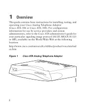
1 Overview This guide contains basic instructions for your Cisco Analog Telephone Adaptor (Cisco ATA 186 or Cisco ATA 188). For configuration information for use by service providers and system administrators, refer to the Cisco ATA administrator's guide for installing, testing, and operating your particular signaling image protocol (SCCP, MGCP, H.323 or SIP), available on the World Wide Web at the following location: http://www.cisco.com/univercd/cc/td/doc/product/voice/ata/ind ex.htm Figure 1 Cisco ATA Analog Telephone Adaptor ANALOCGISTCELOEPAHTONAE1A8D6APTOR 2 72209
1 Overview This guide contains basic instructions for your Cisco Analog Telephone Adaptor (Cisco ATA 186 or Cisco ATA 188). For configuration information for use by service providers and system administrators, refer to the Cisco ATA administrator's guide for installing, testing, and operating your particular signaling image protocol (SCCP, MGCP, H.323 or SIP), available on the World Wide Web at the following location: http://www.cisco.com/univercd/cc/td/doc/product/voice/ata/ind ex.htm Figure 1 Cisco ATA Analog Telephone Adaptor ANALOCGISTCELOEPAHTONAE1A8D6APTOR 2 72209

User Guide
Page 3
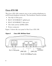
Cisco ATA 186 The Cisco ATA 186 connects one or two analog telephones to an IP-based telephony network. Figure 2 Cisco ATA 186 Rear Panel 72210 PHONE 1 PHONE 2 10BaseT ACT 5V RJ-11 FXS ports RJ-45 10BaseT Power connector ACT LED 3 The hardware features include: • Function button • Two RJ-11 FXS ports • RJ-45 10BASE-T uplink port • Network activity (ACT) LED • Power connector Figure 2 shows the rear panel of the Cisco ATA 186.
Cisco ATA 186 The Cisco ATA 186 connects one or two analog telephones to an IP-based telephony network. Figure 2 Cisco ATA 186 Rear Panel 72210 PHONE 1 PHONE 2 10BaseT ACT 5V RJ-11 FXS ports RJ-45 10BaseT Power connector ACT LED 3 The hardware features include: • Function button • Two RJ-11 FXS ports • RJ-45 10BASE-T uplink port • Network activity (ACT) LED • Power connector Figure 2 shows the rear panel of the Cisco ATA 186.
User Guide
Page 4
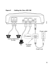
The hardware features include: • Two RJ-11 FXS ports • RJ-45 10/100BASE-T uplink port • RJ-45 10/100BASE-T data port • Two link activity (LINK) LEDs • Power connector Figure 3 shows the rear panel of the Cisco ATA 188. Cisco ATA 188 The Cisco ATA 188 connects one or two analog telephones to an IP-based telephony network. Figure 3 Cisco ATA 188 Rear Panel 72211 PHONE 1 PHONE 2 LINK 10/100 PC 10/100 UPLINK LINK 5V RJ-11 FXS ports LINK LED Power connector LINK LED RJ-45 10/100BaseT ports 4
The hardware features include: • Two RJ-11 FXS ports • RJ-45 10/100BASE-T uplink port • RJ-45 10/100BASE-T data port • Two link activity (LINK) LEDs • Power connector Figure 3 shows the rear panel of the Cisco ATA 188. Cisco ATA 188 The Cisco ATA 188 connects one or two analog telephones to an IP-based telephony network. Figure 3 Cisco ATA 188 Rear Panel 72211 PHONE 1 PHONE 2 LINK 10/100 PC 10/100 UPLINK LINK 5V RJ-11 FXS ports LINK LED Power connector LINK LED RJ-45 10/100BaseT ports 4

User Guide
Page 5
...symbol means danger. Statement 1071 SAVE THESE INSTRUCTIONS Waarschuwing BELANGRIJKE VEILIGHEIDSINSTRUCTIES Dit waarschuwingssymbool betekent gevaar. Use the statement number provided at the end of the hazards involved with standard practices for preventing accidents. Before you work on any action that could cause bodily ... circuitry and be aware of each warning to locate its translation in a situation that creates a potential hazard to people or makes the equipment unsafe. Voordat u aan enige apparatuur gaat werken, dient u zich bewust te zijn van de bij elektrische schakelingen ...
...symbol means danger. Statement 1071 SAVE THESE INSTRUCTIONS Waarschuwing BELANGRIJKE VEILIGHEIDSINSTRUCTIES Dit waarschuwingssymbool betekent gevaar. Use the statement number provided at the end of the hazards involved with standard practices for preventing accidents. Before you work on any action that could cause bodily ... circuitry and be aware of each warning to locate its translation in a situation that creates a potential hazard to people or makes the equipment unsafe. Voordat u aan enige apparatuur gaat werken, dient u zich bewust te zijn van de bij elektrische schakelingen ...

User Guide
Page 9
... this product should be accessible at all national laws and regulations. Do not touch the RJ-11 (phone) port wires (conductors), the conductors of a cable connected to its power source. Warning Read the installation instructions before you connect the system to the RJ-11 port, or the associated circuit-board when the ringer is activated (indicated by a clicking sound) by an incoming call.
... this product should be accessible at all national laws and regulations. Do not touch the RJ-11 (phone) port wires (conductors), the conductors of a cable connected to its power source. Warning Read the installation instructions before you connect the system to the RJ-11 port, or the associated circuit-board when the ringer is activated (indicated by a clicking sound) by an incoming call.

User Guide
Page 10
... connect safety extra-low voltage (SELV) circuits to be installed and maintained by service personnel only as defined by AS/NZS 3260 Clause 1.2.14.3 Service Personnel. Warning This equipment is to telephone-network voltage (TNV) circuits. Warning Do not work on page 13 before you connect the system to its power source. 10 Use caution when connecting cables. Caution Read the instructions in the "Installation...
... connect safety extra-low voltage (SELV) circuits to be installed and maintained by service personnel only as defined by AS/NZS 3260 Clause 1.2.14.3 Service Personnel. Warning This equipment is to telephone-network voltage (TNV) circuits. Warning Do not work on page 13 before you connect the system to its power source. 10 Use caution when connecting cables. Caution Read the instructions in the "Installation...

User Guide
Page 12
... cables for both uplink and data port connections. • Access to another Ethernet device (such as a router or PC) without quality degradation. Otherwise, use a crossover Ethernet cable to connect the Cisco ATA to an IP network • One or two analog Touch-Tone telephones or fax machines, or one of each Ethernet connection. A Category-3 Ethernet cable supports 10BASE-T for up to 100 meters...
... cables for both uplink and data port connections. • Access to another Ethernet device (such as a router or PC) without quality degradation. Otherwise, use a crossover Ethernet cable to connect the Cisco ATA to an IP network • One or two analog Touch-Tone telephones or fax machines, or one of each Ethernet connection. A Category-3 Ethernet cable supports 10BASE-T for up to 100 meters...

User Guide
Page 14
72212 Figure 4 Cabling the Cisco ATA 186 PHONE 1 PHONE 2 10BaseT ACT 5V Analog telephones (or fax) IP network 5V power adaptor Power outlet Power cord 14
72212 Figure 4 Cabling the Cisco ATA 186 PHONE 1 PHONE 2 10BaseT ACT 5V Analog telephones (or fax) IP network 5V power adaptor Power outlet Power cord 14
User Guide
Page 15
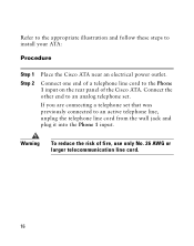
Figure 5 Cabling the Cisco ATA 188 72213 PHONE 1 PHONE 2 LINK 10/100 PC 10/100 UPLINK LINK 5V Analog telephones (or fax) IP network PC 5V power adaptor Power outlet Power cord 15
Figure 5 Cabling the Cisco ATA 188 72213 PHONE 1 PHONE 2 LINK 10/100 PC 10/100 UPLINK LINK 5V Analog telephones (or fax) IP network PC 5V power adaptor Power outlet Power cord 15
User Guide
Page 16
... 1 Step 2 Place the Cisco ATA near an electrical power outlet. Refer to the appropriate illustration and follow these steps to the Phone 1 input on the rear panel of the Cisco ATA. If you are connecting a telephone set . Connect the other end to an analog telephone set that was previously connected to an active telephone line, unplug the telephone line cord from the wall jack and plug it...
... 1 Step 2 Place the Cisco ATA near an electrical power outlet. Refer to the appropriate illustration and follow these steps to the Phone 1 input on the rear panel of the Cisco ATA. If you are connecting a telephone set . Connect the other end to an analog telephone set that was previously connected to an active telephone line, unplug the telephone line cord from the wall jack and plug it...
User Guide
Page 17
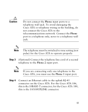
... to the telecommunications network. To avoid damaging the Cisco ATA or telephone wiring in the building, do not connect the Cisco ATA to the uplink RJ-45 connector on the Cisco ATA. Note The telephone must use the Phone 1 input port. For the Cisco ATA 186, this is the 10BASE-T connector; for the Cisco ATA to a telephone wall jack. Connect the Phone port to a telephone only, never to...
... to the telecommunications network. To avoid damaging the Cisco ATA or telephone wiring in the building, do not connect the Cisco ATA to the uplink RJ-45 connector on the Cisco ATA. Note The telephone must use the Phone 1 input port. For the Cisco ATA 186, this is the 10BASE-T connector; for the Cisco ATA to a telephone wall jack. Connect the Phone port to a telephone only, never to...
User Guide
Page 19
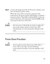
... activity LED flashes to indicate network activity. Caution Do not cover or block the air vents on the rear panel of the 5V DC power adaptor cord into an electrical power outlet. Power-Down Procedure Caution If you need to power down Cisco ATA 186 or Cisco 188 at any time, use the following power-down procedure to prevent damage to the unit. Step 8 Connect the...
... activity LED flashes to indicate network activity. Caution Do not cover or block the air vents on the rear panel of the 5V DC power adaptor cord into an electrical power outlet. Power-Down Procedure Caution If you need to power down Cisco ATA 186 or Cisco 188 at any time, use the following power-down procedure to prevent damage to the unit. Step 8 Connect the...
User Guide
Page 20
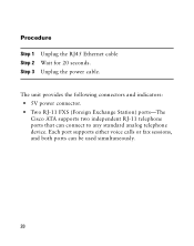
Procedure Step 1 Step 2 Step 3 Unplug the RJ45 Ethernet cable Wait for 20 seconds. Each port supports either voice calls or fax sessions, and both ports can connect to any standard analog telephone device. The unit provides the following connectors and indicators: • 5V power connector. • Two RJ-11 FXS (Foreign Exchange Station) ports-The Cisco ATA supports two independent RJ-11 telephone ports that can be used simultaneously. 20 Unplug the power cable.
Procedure Step 1 Step 2 Step 3 Unplug the RJ45 Ethernet cable Wait for 20 seconds. Each port supports either voice calls or fax sessions, and both ports can connect to any standard analog telephone device. The unit provides the following connectors and indicators: • 5V power connector. • Two RJ-11 FXS (Foreign Exchange Station) ports-The Cisco ATA supports two independent RJ-11 telephone ports that can be used simultaneously. 20 Unplug the power cable.
User Guide
Page 21
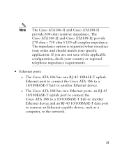
The Cisco ATA186-I2 and Cisco ATA188-I2 provide 270 ohm + 750 ohm // 150-nF complex impedance. The impedance option is requested when you are not sure of the applicable configuration, check your specific application. The Cisco ATA 186 has one RJ-45 10BASE-T uplink Ethernet port to connect the Cisco ATA 186 to the network. 21 Note The Cisco ATA186-I1 and Cisco ATA188-I1 provide...
The Cisco ATA186-I2 and Cisco ATA188-I2 provide 270 ohm + 750 ohm // 150-nF complex impedance. The impedance option is requested when you are not sure of the applicable configuration, check your specific application. The Cisco ATA 186 has one RJ-45 10BASE-T uplink Ethernet port to connect the Cisco ATA 186 to the network. 21 Note The Cisco ATA186-I1 and Cisco ATA188-I1 provide...
User Guide
Page 22
... performs auto-negotiation for duplexity and speed and is capable of the unit (see Figure 6). 22 The LED blinks to show network activity and is solid when there is a link. • The Cisco ATA 186 RJ-45 LED is solid when the Cisco ATA is powered on and blinks to show network activity. • Function button-The function button is located on , then turns...
... performs auto-negotiation for duplexity and speed and is capable of the unit (see Figure 6). 22 The LED blinks to show network activity and is solid when there is a link. • The Cisco ATA 186 RJ-45 LED is solid when the Cisco ATA is powered on and blinks to show network activity. • Function button-The function button is located on , then turns...

User Guide
Page 23
Note If the function button blinks slowly, the Cisco ATA cannot find the DHCP server. Figure 6 Cisco ATA Function Button Function button 72214 ANALOCGISTCELOEPAHTONAE1A8D6APTOR The function button lights when you pick up the handset of a telephone attached to the Cisco ATA. Check your Ethernet connections and make sure the DHCP server is upgrading its configuration. The button blinks quickly when the Cisco ATA is available. 23
Note If the function button blinks slowly, the Cisco ATA cannot find the DHCP server. Figure 6 Cisco ATA Function Button Function button 72214 ANALOCGISTCELOEPAHTONAE1A8D6APTOR The function button lights when you pick up the handset of a telephone attached to the Cisco ATA. Check your Ethernet connections and make sure the DHCP server is upgrading its configuration. The button blinks quickly when the Cisco ATA is available. 23

User Guide
Page 24
... voice configuration menu in your administrator's guide. The Cisco ATA administrator's guides are using (SCCP, MGCP, H.323 or SIP). Doing so may interfere with the process and may permanently disable the Cisco ATA. 3 Configuration For complete configuration information, see the information about the voice configuration menu, see the administrator's guide for the signaling image protocol you to access to the voice configuration menu. Caution Never press the function button during an upgrade...
... voice configuration menu in your administrator's guide. The Cisco ATA administrator's guides are using (SCCP, MGCP, H.323 or SIP). Doing so may interfere with the process and may permanently disable the Cisco ATA. 3 Configuration For complete configuration information, see the information about the voice configuration menu, see the administrator's guide for the signaling image protocol you to access to the voice configuration menu. Caution Never press the function button during an upgrade...
User Guide
Page 25
... place calls using the preceding instructions, contact your call by hanging up when finished. You can cancel or discontinue your service provider or system administrator for assistance. Make a call as you connect the Ethernet cable, make a separate, simultaneous telephone call at any time by using the second handset connected to acquire the DHCP configuration. • If the green activity LED is not flashing after you normally do. Troubleshooting Tips...
... place calls using the preceding instructions, contact your call by hanging up when finished. You can cancel or discontinue your service provider or system administrator for assistance. Make a call as you connect the Ethernet cable, make a separate, simultaneous telephone call at any time by using the second handset connected to acquire the DHCP configuration. • If the green activity LED is not flashing after you normally do. Troubleshooting Tips...
User Guide
Page 26
... should show an incoming request from the telephone is plugged into the appropriate port on the Cisco ATA. Try your call again later. A fast-busy tone indicates that the telephone line cord from the MAC address listed on the product label or given by the voice prompt. Test another phone; • If there is no dial tone, make sure that you called is properly registered on your Call Control system.
... should show an incoming request from the telephone is plugged into the appropriate port on the Cisco ATA. Try your call again later. A fast-busy tone indicates that the telephone line cord from the MAC address listed on the product label or given by the voice prompt. Test another phone; • If there is no dial tone, make sure that you called is properly registered on your Call Control system.

User Guide
Page 28
Changing the Way We Work, Live, Play, and Learn is a service mark of Cisco Systems, Inc.; All other trademarks mentioned in the USA on recycled paper containing 10% postconsumer waste. 78-15931-01 The use of the word partner does not imply a partnership relationship between Cisco and any other countries. CCVP, the Cisco logo, and the Cisco Square Bridge logo...
Changing the Way We Work, Live, Play, and Learn is a service mark of Cisco Systems, Inc.; All other trademarks mentioned in the USA on recycled paper containing 10% postconsumer waste. 78-15931-01 The use of the word partner does not imply a partnership relationship between Cisco and any other countries. CCVP, the Cisco logo, and the Cisco Square Bridge logo...


