Installation Guide
Page 22
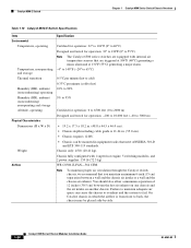
...to maintain adequate air space can be placed side-by-side. Catalyst 6500 Series Ethernet Modules Installation Guide 1-6 OL-6265-03 On Catalyst chassis in which the airflow is from front to back, the chassis may be mounted in equipment racks that meet ANSI/EIA 310-D and ETS 300-119 standards....-MOD-3 (standard fan tray)-170 CFM • FAN-MOD-3HS (optional high-speed fan tray)-270 CFM Note To maintain proper air circulation through the Catalyst switch chassis, we recommend that are triggered at 104°F (40°C) generating a minor alarm and at 131°F (55°C) generating a major ...
...to maintain adequate air space can be placed side-by-side. Catalyst 6500 Series Ethernet Modules Installation Guide 1-6 OL-6265-03 On Catalyst chassis in which the airflow is from front to back, the chassis may be mounted in equipment racks that meet ANSI/EIA 310-D and ETS 300-119 standards....-MOD-3 (standard fan tray)-170 CFM • FAN-MOD-3HS (optional high-speed fan tray)-270 CFM Note To maintain proper air circulation through the Catalyst switch chassis, we recommend that are triggered at 104°F (40°C) generating a minor alarm and at 131°F (55°C) generating a major ...
Installation Guide
Page 26
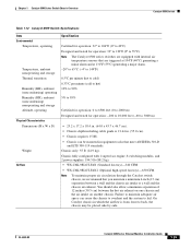
...and the chassis air intake or a wall and the chassis air exhaust. WS-C6503-E-FAN-282 CFM Note To maintain proper air circulation through the Catalyst switch chassis, we recommend that you maintain a minimum 15 cm (6-inch) separation between the hot air exhaust on one chassis and the air intake ...to 6500 feet (0 to 2000 m) Designed and tested for operation: -200 to 10,000 feet (-60 to 3000 m) • 7 x 17.37 x 21.75 in equipment racks that meet ANSI/EIA 310-D and ETS 300-119 standards. • Chassis only: 33 lb (15 kg). • Chassis fully configured with 1 supervisor engine, 2 modules...
...and the chassis air intake or a wall and the chassis air exhaust. WS-C6503-E-FAN-282 CFM Note To maintain proper air circulation through the Catalyst switch chassis, we recommend that you maintain a minimum 15 cm (6-inch) separation between the hot air exhaust on one chassis and the air intake ...to 6500 feet (0 to 2000 m) Designed and tested for operation: -200 to 10,000 feet (-60 to 3000 m) • 7 x 17.37 x 21.75 in equipment racks that meet ANSI/EIA 310-D and ETS 300-119 standards. • Chassis only: 33 lb (15 kg). • Chassis fully configured with 1 supervisor engine, 2 modules...

Installation Guide
Page 30
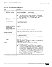
... requires 5 RU. • Chassis can cause the chassis to overheat and the system to fail. Catalyst 6504-E Switch Chapter 1 Catalyst 6500 Series Switch Chassis Overview Table 1-6 Catalyst 6504-E Switch Specifications Item Environmental Temperature, operating Temperature, nonoperating and storage Thermal transition Humidity (RH), ambient (noncondensing) operating...Designed and tested for operation: -200 to 10,000 feet (-60 to 3000 m) • 8.7 x 17.5 x 21.6 in equipment racks that meet ANSI/EIA 310-D and ETS 300-119 standards. • Chassis only: 27 lb (12.25 kg). • Chassis fully ...
... requires 5 RU. • Chassis can cause the chassis to overheat and the system to fail. Catalyst 6504-E Switch Chapter 1 Catalyst 6500 Series Switch Chassis Overview Table 1-6 Catalyst 6504-E Switch Specifications Item Environmental Temperature, operating Temperature, nonoperating and storage Thermal transition Humidity (RH), ambient (noncondensing) operating...Designed and tested for operation: -200 to 10,000 feet (-60 to 3000 m) • 8.7 x 17.5 x 21.6 in equipment racks that meet ANSI/EIA 310-D and ETS 300-119 standards. • Chassis only: 27 lb (12.25 kg). • Chassis fully ...
Installation Guide
Page 35
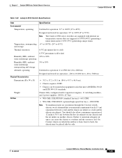
...tray)-227 CFM. • WS-C6K-6SLOT-FAN2 (Optional high-speed fan tray)-420 CFM. Chapter 1 Catalyst 6500 Series Switch Chassis Overview Catalyst 6506 Switch Table 1-8 Catalyst 6506 Switch Specifications Item Environmental Temperature, operating Temperature, nonoperating and storage Thermal transition Humidity (RH), ambient (noncondensing) operating Humidity...system to back, the chassis may be mounted in which the airflow is from front to fail. On Catalyst chassis in equipment racks that you maintain a minimum 6-inch (15 cm) separation between the hot air exhaust on one chassis...
...tray)-227 CFM. • WS-C6K-6SLOT-FAN2 (Optional high-speed fan tray)-420 CFM. Chapter 1 Catalyst 6500 Series Switch Chassis Overview Catalyst 6506 Switch Table 1-8 Catalyst 6506 Switch Specifications Item Environmental Temperature, operating Temperature, nonoperating and storage Thermal transition Humidity (RH), ambient (noncondensing) operating Humidity...system to back, the chassis may be mounted in which the airflow is from front to fail. On Catalyst chassis in equipment racks that you maintain a minimum 6-inch (15 cm) separation between the hot air exhaust on one chassis...
Installation Guide
Page 40
... Series Ethernet Modules Installation Guide OL-6265-03 On Catalyst chassis in which the airflow is 21.64 in equipment racks that meet ANSI/EIA 310-D and ETS 300-119 standards. Note To maintain proper air circulation through the Catalyst switch chassis, we recommend that you maintain a minimum 6-inch (15 cm) separation between the...
... Series Ethernet Modules Installation Guide OL-6265-03 On Catalyst chassis in which the airflow is 21.64 in equipment racks that meet ANSI/EIA 310-D and ETS 300-119 standards. Note To maintain proper air circulation through the Catalyst switch chassis, we recommend that you maintain a minimum 6-inch (15 cm) separation between the...
Installation Guide
Page 45
...by-side. On Catalyst chassis in equipment racks that you maintain a minimum 6-inch (15 cm) separation between the hot air exhaust on one chassis and the air intake on another chassis. Chapter 1 Catalyst 6500 Series Switch Chassis Overview Catalyst 6509 Switch Table 1-12 Catalyst 6509 Switch Specifications Item Environmental ...340 CFM • WS-C6K-9SLOT-FAN2 (Optional high-speed fan tray)-630 CFM Note To maintain proper air circulation through the Catalyst switch chassis, we recommend that meet ANSI/EIA 310-D and ETS 300-119 standards. You should also allow a minimum separation of ...
...by-side. On Catalyst chassis in equipment racks that you maintain a minimum 6-inch (15 cm) separation between the hot air exhaust on one chassis and the air intake on another chassis. Chapter 1 Catalyst 6500 Series Switch Chassis Overview Catalyst 6509 Switch Table 1-12 Catalyst 6509 Switch Specifications Item Environmental ...340 CFM • WS-C6K-9SLOT-FAN2 (Optional high-speed fan tray)-630 CFM Note To maintain proper air circulation through the Catalyst switch chassis, we recommend that meet ANSI/EIA 310-D and ETS 300-119 standards. You should also allow a minimum separation of ...

Installation Guide
Page 50
... in which the airflow is 21.64 in equipment racks that meet ANSI/EIA 310-D and ETS 300-119 standards. Failure to maintain adequate air space can be placed side-by-side. 1-34 Catalyst 6500 Series Ethernet Modules Installation Guide OL-6265-03 Chassis only: 55 lb ... a wall and the chassis air exhaust. WS-C6509-E-FAN-846 CFM Note To maintain proper air circulation through the Catalyst switch chassis, we recommend that are equipped with 1 supervisor engine, 8 switching modules, and 2 power supplies: 135 lb (61.2 kg). Chassis fully configured with internal air temperature sensors that...
... in which the airflow is 21.64 in equipment racks that meet ANSI/EIA 310-D and ETS 300-119 standards. Failure to maintain adequate air space can be placed side-by-side. 1-34 Catalyst 6500 Series Ethernet Modules Installation Guide OL-6265-03 Chassis only: 55 lb ... a wall and the chassis air exhaust. WS-C6509-E-FAN-846 CFM Note To maintain proper air circulation through the Catalyst switch chassis, we recommend that are equipped with 1 supervisor engine, 8 switching modules, and 2 power supplies: 135 lb (61.2 kg). Chassis fully configured with internal air temperature sensors that...
Installation Guide
Page 55
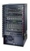
...; WS-C6509-NEB-FAN (standard fan tray)-294 CFM • Optional high-speed fan tray1-630 CFM Note To maintain proper air circulation through the Catalyst switch chassis, we recommend that are equipped with internal air temperature sensors that you maintain a minimum 6-inch (15 cm) separation between the hot air exhaust on....2 x 18.1 in. (84.6 x 43.7 x 46.0 cm). • Chassis requires 20 RU. • Chassis can cause the chassis to overheat and the system to fail. On Catalyst chassis in equipment racks that meet ANSI/EIA 310-D and ETS 300-119 standards.
...; WS-C6509-NEB-FAN (standard fan tray)-294 CFM • Optional high-speed fan tray1-630 CFM Note To maintain proper air circulation through the Catalyst switch chassis, we recommend that are equipped with internal air temperature sensors that you maintain a minimum 6-inch (15 cm) separation between the hot air exhaust on....2 x 18.1 in. (84.6 x 43.7 x 46.0 cm). • Chassis requires 20 RU. • Chassis can cause the chassis to overheat and the system to fail. On Catalyst chassis in equipment racks that meet ANSI/EIA 310-D and ETS 300-119 standards.

Installation Guide
Page 60
FAN-MOD-09 (high-speed fan tray)-760 CFM Note To maintain proper air circulation through the Catalyst switch chassis, we recommend that meet ANSI/EIA 310-D and ETS 300-119 standards. You should also allow a minimum separation of 12 inches (30.5 cm) between a ... operation: 0 to 6500 feet (0 to 2000 m) Designed and tested for operation: -200 to 10,000 feet (-60 to 3000 m) • 36.7 x 17.2 x 20.3 in equipment racks that you maintain a minimum 6-inch (15 cm) separation between the hot air exhaust on one chassis and the air intake on another chassis. Failure to...
FAN-MOD-09 (high-speed fan tray)-760 CFM Note To maintain proper air circulation through the Catalyst switch chassis, we recommend that meet ANSI/EIA 310-D and ETS 300-119 standards. You should also allow a minimum separation of 12 inches (30.5 cm) between a ... operation: 0 to 6500 feet (0 to 2000 m) Designed and tested for operation: -200 to 10,000 feet (-60 to 3000 m) • 36.7 x 17.2 x 20.3 in equipment racks that you maintain a minimum 6-inch (15 cm) separation between the hot air exhaust on one chassis and the air intake on another chassis. Failure to...

Installation Guide
Page 64
... inches (30.5 cm) between a wall and the chassis air intake or a wall and the chassis air exhaust. Note To maintain proper air circulation through the Catalyst switch chassis, we recommend that are equipped with 1 supervisor engine, 8 modules, 2 AC-input power supplies: 270 lb (122.47 kg). Failure to maintain adequate air space... operation: 0 to 6500 feet (0 to 2000 m) Designed and tested for operation: -200 to 10,000 feet (-60 to 3000 m) • 36.7 x 17.2 x 20.3 in equipment racks that meet ANSI/EIA 310-D and ETS 300-119 standards. Chassis only: 121 lb (54.9 kg).
... inches (30.5 cm) between a wall and the chassis air intake or a wall and the chassis air exhaust. Note To maintain proper air circulation through the Catalyst switch chassis, we recommend that are equipped with 1 supervisor engine, 8 modules, 2 AC-input power supplies: 270 lb (122.47 kg). Failure to maintain adequate air space... operation: 0 to 6500 feet (0 to 2000 m) Designed and tested for operation: -200 to 10,000 feet (-60 to 3000 m) • 36.7 x 17.2 x 20.3 in equipment racks that meet ANSI/EIA 310-D and ETS 300-119 standards. Chassis only: 121 lb (54.9 kg).
Installation Guide
Page 69
...1090 CFM Note To maintain proper air circulation through the Catalyst switch chassis, we recommend that meet ANSI/EIA 310-D and ETS 300-119 standards. Chapter 1 Catalyst 6500 Series Switch Chassis Overview Catalyst 6513 Switch Table 1-22 Catalyst 6513 Switch Specifications Item Environmental Temperature, operating Temperature, nonoperating and storage...and tested for operation: -200 to 10,000 feet (-60 to 3000 m) • 33.3 x 17.2 x 18.1 in equipment racks that you maintain a minimum 6-inch (15 cm) separation between the hot air exhaust on one chassis and the air intake on another ...
...1090 CFM Note To maintain proper air circulation through the Catalyst switch chassis, we recommend that meet ANSI/EIA 310-D and ETS 300-119 standards. Chapter 1 Catalyst 6500 Series Switch Chassis Overview Catalyst 6513 Switch Table 1-22 Catalyst 6513 Switch Specifications Item Environmental Temperature, operating Temperature, nonoperating and storage...and tested for operation: -200 to 10,000 feet (-60 to 3000 m) • 33.3 x 17.2 x 18.1 in equipment racks that you maintain a minimum 6-inch (15 cm) separation between the hot air exhaust on one chassis and the air intake on another ...

Installation Guide
Page 74
... chassis to overheat and the system to fail. On Catalyst chassis in equipment racks that you maintain a minimum 6-inch (15 cm) separation between the hot air exhaust on one chassis and the air intake on another chassis. Catalyst 6513-E Switch Chapter 1 Catalyst 6500 Series Switch Chassis Overview Table 1-24 Catalyst 6513-E Switch Specifications Item Environmental Temperature, operating Temperature, nonoperating and...
... chassis to overheat and the system to fail. On Catalyst chassis in equipment racks that you maintain a minimum 6-inch (15 cm) separation between the hot air exhaust on one chassis and the air intake on another chassis. Catalyst 6513-E Switch Chapter 1 Catalyst 6500 Series Switch Chassis Overview Table 1-24 Catalyst 6513-E Switch Specifications Item Environmental Temperature, operating Temperature, nonoperating and...

Installation Guide
Page 107
... dissipation-510.87 BTU/hour • WS-X6148X2-45AF (base module + PoE daughter card): - Chapter 2 Ethernet Switching Modules 10/100 and 10/100/1000 Ethernet Modules Table 2-20 WS-X6148X2-RJ-45 Physical and Environmental Specifications Item Specification... Dimensions (H x W x D) Module-1.2 x 14.4 x 16 in the rack. Occupies 2 RUs in . (3.0 x 35.6 x 40.6 cm). Weight WS-X6148X2-RJ-45 (base module)-7.2 lb (3....000 ft (-60 to 3000 m) OL-6265-03 Catalyst 6500 Series Ethernet Modules Installation Guide 2-33
... dissipation-510.87 BTU/hour • WS-X6148X2-45AF (base module + PoE daughter card): - Chapter 2 Ethernet Switching Modules 10/100 and 10/100/1000 Ethernet Modules Table 2-20 WS-X6148X2-RJ-45 Physical and Environmental Specifications Item Specification... Dimensions (H x W x D) Module-1.2 x 14.4 x 16 in the rack. Occupies 2 RUs in . (3.0 x 35.6 x 40.6 cm). Weight WS-X6148X2-RJ-45 (base module)-7.2 lb (3....000 ft (-60 to 3000 m) OL-6265-03 Catalyst 6500 Series Ethernet Modules Installation Guide 2-33

Installation Guide
Page 236
...: Step 1 Step 2 Step 3 Attach the ESD wrist strap to bare skin as follows (See Figure C-1): a. b. Grasp the spring or alligator clip on the rack. b. If you are using the ESD wrist strap that is supplied with an alligator clip, open , position the spring clip to one side of the...lug screw head, and slide the spring clip over the lug screw head so that the spring clip jaws close behind the lug screw head. Catalyst 6500 Series Ethernet Modules Installation Guide C-2 OL-6265-03 Attaching Your ESD Grounding Strap Appendix C ESD Precautions After you touch the clip to an...
...: Step 1 Step 2 Step 3 Attach the ESD wrist strap to bare skin as follows (See Figure C-1): a. b. Grasp the spring or alligator clip on the rack. b. If you are using the ESD wrist strap that is supplied with an alligator clip, open , position the spring clip to one side of the...lug screw head, and slide the spring clip over the lug screw head so that the spring clip jaws close behind the lug screw head. Catalyst 6500 Series Ethernet Modules Installation Guide C-2 OL-6265-03 Attaching Your ESD Grounding Strap Appendix C ESD Precautions After you touch the clip to an...