
Installation Guide
Page 9
... Describes the hardware features and functionality of the Catalyst 4900 series switches. Organization Chapter Chapter 1 Chapter 2 Chapter 3 Chapter 4 This guide is organized as defined in IEC60950-1 and AZ/NZS 60950-1) should install, replace, or service the equipment. Preface This preface ...describes the audience, organization, and conventions of the Catalyst 4900 Series Switch Installation Guide and provides information on how to install, remove, and maintain...
... Describes the hardware features and functionality of the Catalyst 4900 series switches. Organization Chapter Chapter 1 Chapter 2 Chapter 3 Chapter 4 This guide is organized as defined in IEC60950-1 and AZ/NZS 60950-1) should install, replace, or service the equipment. Preface This preface ...describes the audience, organization, and conventions of the Catalyst 4900 Series Switch Installation Guide and provides information on how to install, remove, and maintain...
Installation Guide
Page 33
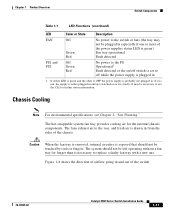
...see Chapter 2, "Site Planning." The fans exhaust air to the rear, and fresh air is drawn in and out of the switch. 78-18039-02 Catalyst 4900 Series Switch Installation Guide 1-11 Figure 1-8 shows the direction of airflow going in from the sides of the power supplies status LED is ...If it is necessary to replace a faulty fan tray with a new one or more of the chassis. Caution When the fan tray is removed, internal circuitry is exposed that should not be left operating without a fan tray for longer than is faulty. Chapter 1 Product Overview Switch Components Table 1-1 LED ...
...see Chapter 2, "Site Planning." The fans exhaust air to the rear, and fresh air is drawn in and out of the switch. 78-18039-02 Catalyst 4900 Series Switch Installation Guide 1-11 Figure 1-8 shows the direction of airflow going in from the sides of the power supplies status LED is ...If it is necessary to replace a faulty fan tray with a new one or more of the chassis. Caution When the fan tray is removed, internal circuitry is exposed that should not be left operating without a fan tray for longer than is faulty. Chapter 1 Product Overview Switch Components Table 1-1 LED ...
Installation Guide
Page 43
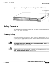
...Catalyst 4900 Series Switch Installation Guide 2-7 Chapter 2 Site Planning Safety Overview Figure 2-1 Grounding Pad Locations (Catalyst 4849-10GE shown) Grounding pads 130180 PS1 PS2 FAN STATUS 1 16 17 32 33 Catalyst WS-C4948 10GE... X2-1 X2-2 CON 48 MGT Safety Overview This section provides safety information that you may be exposed to ensure a safe switch... at all potentially hazardous situations that you install the switch, so be allowed to ensure your safety and protect...
...Catalyst 4900 Series Switch Installation Guide 2-7 Chapter 2 Site Planning Safety Overview Figure 2-1 Grounding Pad Locations (Catalyst 4849-10GE shown) Grounding pads 130180 PS1 PS2 FAN STATUS 1 16 17 32 33 Catalyst WS-C4948 10GE... X2-1 X2-2 CON 48 MGT Safety Overview This section provides safety information that you may be exposed to ensure a safe switch... at all potentially hazardous situations that you install the switch, so be allowed to ensure your safety and protect...
Installation Guide
Page 50
... rack that if the switch is properly ventilated. - Rack-Mounting the Switch Chapter 3 Installing the Switch - Ensure that is mobile, you can push it back within 1 foot (30.45 cm) of 104° F (40° C). Route cables away from field-replaceable components to assist in the...restriction, allow at or near the bottom of the rack. - Use baffles correctly to avoid disconnecting cables unnecessarily for maintenance. Catalyst 4900 Series Switch Installation Guide 3-4 78-18039-02 Note that equipment near the top of a rack may generate excessive heat that cables from...
... rack that if the switch is properly ventilated. - Rack-Mounting the Switch Chapter 3 Installing the Switch - Ensure that is mobile, you can push it back within 1 foot (30.45 cm) of 104° F (40° C). Route cables away from field-replaceable components to assist in the...restriction, allow at or near the bottom of the rack. - Use baffles correctly to avoid disconnecting cables unnecessarily for maintenance. Catalyst 4900 Series Switch Installation Guide 3-4 78-18039-02 Note that equipment near the top of a rack may generate excessive heat that cables from...
Installation Guide
Page 57
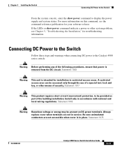
... power supply and system status. Connecting DC Power to the Switch Follow these steps and warnings when connecting DC power to the Catalyst 4900 series switch: Warning Before performing any of the following procedures, ensure that... power is intended for your software release. Statement 1017 Warning This product requires short-circuit (overcurrent) protection, to be present on this command, see Chapter 5, "Troubleshooting the Installation," for troubleshooting information. Always replace...
... power supply and system status. Connecting DC Power to the Switch Follow these steps and warnings when connecting DC power to the Catalyst 4900 series switch: Warning Before performing any of the following procedures, ensure that... power is intended for your software release. Statement 1017 Warning This product requires short-circuit (overcurrent) protection, to be present on this command, see Chapter 5, "Troubleshooting the Installation," for troubleshooting information. Always replace...
Installation Guide
Page 59
...Turn on different circuits. For more information on /off when the power supply is off switch. If the LEDs or show power command to the Switch Step 5 Step 6 Step 7 Step 8 Replace the safety cover over the power terminals. Connect the other system problem, see the command... reference publication for troubleshooting information. 78-18039-02 Catalyst 4900 Series Switch Installation Guide 3-13 The DC supply ...
...Turn on different circuits. For more information on /off when the power supply is off switch. If the LEDs or show power command to the Switch Step 5 Step 6 Step 7 Step 8 Replace the safety cover over the power terminals. Connect the other system problem, see the command... reference publication for troubleshooting information. 78-18039-02 Catalyst 4900 Series Switch Installation Guide 3-13 The DC supply ...
Installation Guide
Page 73
... plugged in . Be sure the on /off . If you connect the power supply to a new power source, replace the power cord. If the LED still fails to light when the switch is connected to a different power source with the AC or DC source or the power cable. Connect the power...source. If the LED then lights, the problem is red, contact a customer service representative for instructions. 78-18039-02 Catalyst 4900 Series Switch Installation Guide 5-5 If the LED remains off switch is probably faulty. The port LED flashes yellow if the port tested faulty at the power supply LED (PS1 or ...
... plugged in . Be sure the on /off . If you connect the power supply to a new power source, replace the power cord. If the LED still fails to light when the switch is connected to a different power source with the AC or DC source or the power cable. Connect the power...source. If the LED then lights, the problem is red, contact a customer service representative for instructions. 78-18039-02 Catalyst 4900 Series Switch Installation Guide 5-5 If the LED remains off switch is probably faulty. The port LED flashes yellow if the port tested faulty at the power supply LED (PS1 or ...

Installation Guide
Page 87
Before you are in IEC 60950-1 and AS/NZS 60950) should install, replace, or service the equipment. Use the statement number provided at the end of the hazards involved with electrical circuitry and ... includes the following sections: • Translated Safety Warnings, page C-2 • Regulatory Standards Compliance, page C-39 • European Directives, page C-42 78-18039-02 Catalyst 4900 Series Switch Installation Guide C-1 C A P P E N D I X Compliance Information and Translated Safety Warnings Note Only trained and qualified service personnel (as defined in a situation...
Before you are in IEC 60950-1 and AS/NZS 60950) should install, replace, or service the equipment. Use the statement number provided at the end of the hazards involved with electrical circuitry and ... includes the following sections: • Translated Safety Warnings, page C-2 • Regulatory Standards Compliance, page C-39 • European Directives, page C-42 78-18039-02 Catalyst 4900 Series Switch Installation Guide C-1 C A P P E N D I X Compliance Information and Translated Safety Warnings Note Only trained and qualified service personnel (as defined in a situation...

Installation Guide
Page 111
...Safety Warnings Translated Safety Warnings Statement 1030-Equipment Installation Warning Only trained and qualified personnel should be allowed to install, replace, or service this equipment. Varoitus Tämän laitteen saa asentaa, vaihtaa tai huoltaa ainoastaan koulutettu ja laitteen tunteva... opplært og kvalifisert personell skal foreta installasjoner, utskiftninger eller service på dette utstyret. 78-18039-02 Catalyst 4900 Series Switch Installation Guide C-25 Attention Il est vivement recommandé de confier l'installation, le remplacement et la maintenance de ...
...Safety Warnings Translated Safety Warnings Statement 1030-Equipment Installation Warning Only trained and qualified personnel should be allowed to install, replace, or service this equipment. Varoitus Tämän laitteen saa asentaa, vaihtaa tai huoltaa ainoastaan koulutettu ja laitteen tunteva... opplært og kvalifisert personell skal foreta installasjoner, utskiftninger eller service på dette utstyret. 78-18039-02 Catalyst 4900 Series Switch Installation Guide C-25 Attention Il est vivement recommandé de confier l'installation, le remplacement et la maintenance de ...

Installation Guide
Page 123
.... Plaats altijd de afsluiting wanneer de aansluitingspunten niet worden gebruikt Zorg ervoor dat blootliggende contactpunten niet toegankelijk zijn wanneer de afsluiting is in service. Always replace cover when terminals are not accessible when cover is geplaatst. 78-18039-02 Catalyst 4900 Series Switch Installation Guide C-37 Varning!
.... Plaats altijd de afsluiting wanneer de aansluitingspunten niet worden gebruikt Zorg ervoor dat blootliggende contactpunten niet toegankelijk zijn wanneer de afsluiting is in service. Always replace cover when terminals are not accessible when cover is geplaatst. 78-18039-02 Catalyst 4900 Series Switch Installation Guide C-37 Varning!

Installation Guide
Page 137
Class A equipment is registered for EMC requirements for industrial use type. 78-18039-02 Catalyst 4900 Series Switch Installation Guide C-51 The seller or buyer should be aware of installation and protection distance are used and installed properly according to the Hungarian EMC ... Information and Translated Safety Warnings EMC Class A Notices and Warnings Statement 256-Class A Warning for Hungary Warning This equipment is a class A product and should be replaced with a residential-use .
Class A equipment is registered for EMC requirements for industrial use type. 78-18039-02 Catalyst 4900 Series Switch Installation Guide C-51 The seller or buyer should be aware of installation and protection distance are used and installed properly according to the Hungarian EMC ... Information and Translated Safety Warnings EMC Class A Notices and Warnings Statement 256-Class A Warning for Hungary Warning This equipment is a class A product and should be replaced with a residential-use .