

Installation Guide
Page 1
Catalyst 4900 Series Switch Installation Guide August 2008 Americas Headquarters Cisco Systems, Inc. 170 West Tasman Drive San Jose, CA 95134-1706 USA http://www.cisco.com Tel: 408 526-4000 800 553-NETS (6387) Fax: 408 527-0883 Text Part Number: 78-18039-02
Catalyst 4900 Series Switch Installation Guide August 2008 Americas Headquarters Cisco Systems, Inc. 170 West Tasman Drive San Jose, CA 95134-1706 USA http://www.cisco.com Tel: 408 526-4000 800 553-NETS (6387) Fax: 408 527-0883 Text Part Number: 78-18039-02
Installation Guide
Page 2
...WITH THE PRODUCT AND ARE INCORPORATED HEREIN BY THIS REFERENCE. This equipment has been tested and found to part 15 of the UNIX operating system. However, there is likely to this manual generates and may be limited by the University of California, Berkeley (UCB) as part of ... stops, it was probably caused by turning it is , make certain the equipment and the television or radio are on circuits controlled by Cisco Systems, Inc. could void the FCC approval and negate your own expense. All rights reserved. NOTWITHSTANDING ANY OTHER WARRANTY HEREIN, ALL DOCUMENT FILES ...
...WITH THE PRODUCT AND ARE INCORPORATED HEREIN BY THIS REFERENCE. This equipment has been tested and found to part 15 of the UNIX operating system. However, there is likely to this manual generates and may be limited by the University of California, Berkeley (UCB) as part of ... stops, it was probably caused by turning it is , make certain the equipment and the television or radio are on circuits controlled by Cisco Systems, Inc. could void the FCC approval and negate your own expense. All rights reserved. NOTWITHSTANDING ANY OTHER WARRANTY HEREIN, ALL DOCUMENT FILES ...
Installation Guide
Page 3
... Access Registrar, Aironet, AsyncOS, Bringing the Meeting To You, Catalyst, CCDA, CCDP, CCIE, CCIP, CCNA, CCNP, CCSP, CCVP, Cisco, the Cisco Certified Internetwork Expert logo, Cisco IOS, Cisco Press, Cisco Systems, Cisco Systems Capital, the Cisco Systems logo, Cisco Unity, Collaboration Without Limitation, EtherFast, EtherSwitch, Event Center, Fast...United States and certain other company. (0807R) Catalyst 4900 Series Switch Installation Guide Copyright © 2008 Cisco Systems, Inc. Changing the Way We Work, Live, Play, and Learn and Cisco Store are trademarks; The use of the word ...
... Access Registrar, Aironet, AsyncOS, Bringing the Meeting To You, Catalyst, CCDA, CCDP, CCIE, CCIP, CCNA, CCNP, CCSP, CCVP, Cisco, the Cisco Certified Internetwork Expert logo, Cisco IOS, Cisco Press, Cisco Systems, Cisco Systems Capital, the Cisco Systems logo, Cisco Unity, Collaboration Without Limitation, EtherFast, EtherSwitch, Event Center, Fast...United States and certain other company. (0807R) Catalyst 4900 Series Switch Installation Guide Copyright © 2008 Cisco Systems, Inc. Changing the Way We Work, Live, Play, and Learn and Cisco Store are trademarks; The use of the word ...

Installation Guide
Page 5
... 1071-Warning Definition xii Obtaining Documentation and Submitting a Service Request xxi Product Overview 1-1 Catalyst 4900 Series Switch Applications 1-2 Catalyst 4948 Switch Software Features 1-3 Catalyst 4948-10GE and Catalyst 4928-10GE Switch Software Features 1-4 Hardware System Features 1-6 Switch Components 1-7 Traffic Ports on the Catalyst 4948 1-7 Traffic Ports on the Catalyst 4948-10GE 1-7 Traffic Ports on the Catalyst 4928-10GE 1-7 Console Port 1-7 Front Panel LEDs 1-9 Chassis Cooling 1-11 Power Supplies 1-12 Environmental...
... 1071-Warning Definition xii Obtaining Documentation and Submitting a Service Request xxi Product Overview 1-1 Catalyst 4900 Series Switch Applications 1-2 Catalyst 4948 Switch Software Features 1-3 Catalyst 4948-10GE and Catalyst 4928-10GE Switch Software Features 1-4 Hardware System Features 1-6 Switch Components 1-7 Traffic Ports on the Catalyst 4948 1-7 Traffic Ports on the Catalyst 4948-10GE 1-7 Traffic Ports on the Catalyst 4928-10GE 1-7 Console Port 1-7 Front Panel LEDs 1-9 Chassis Cooling 1-11 Power Supplies 1-12 Environmental...
Installation Guide
Page 6
... Modules and Alternative Wiring 4-1 X2 Modules 4-2 Module Maintenance Guidelines 4-5 Cleaning the Fiber-Optic Connectors 4-5 Additional Guidelines 4-7 Troubleshooting the Installation 5-1 Getting Started 5-2 Problem Solving to the System Component Level 5-2 Identifying Startup Problems 5-3 LED Readings 5-3 Troubleshooting the Power Supply 5-5 Contacting Customer Service 5-6 Specifications A-1 Console Port A-1 Catalyst 4900 Series Switch Installation Guide vi 78-18039-02
... Modules and Alternative Wiring 4-1 X2 Modules 4-2 Module Maintenance Guidelines 4-5 Cleaning the Fiber-Optic Connectors 4-5 Additional Guidelines 4-7 Troubleshooting the Installation 5-1 Getting Started 5-2 Problem Solving to the System Component Level 5-2 Identifying Startup Problems 5-3 LED Readings 5-3 Troubleshooting the Power Supply 5-5 Contacting Customer Service 5-6 Specifications A-1 Console Port A-1 Catalyst 4900 Series Switch Installation Guide vi 78-18039-02
Installation Guide
Page 10
... your software release: • Catalyst 4500 Series Switch Cisco IOS Software Configuration Guide http://www.cisco.com/en/US/products/hw/switches/ps4324/products_install ation_and_configuration_guides_list.html • Catalyst 4500 Series Switch Cisco IOS Command Reference http://www.cisco.com/en/US/products/hw/switches/ps4324/prod_command _reference_list.html • Catalyst 4500 Series Switch Cisco IOS System Message Guide http://www.cisco.com/en/US/products...
... your software release: • Catalyst 4500 Series Switch Cisco IOS Software Configuration Guide http://www.cisco.com/en/US/products/hw/switches/ps4324/products_install ation_and_configuration_guides_list.html • Catalyst 4500 Series Switch Cisco IOS Command Reference http://www.cisco.com/en/US/products/hw/switches/ps4324/prod_command _reference_list.html • Catalyst 4500 Series Switch Cisco IOS System Message Guide http://www.cisco.com/en/US/products...
Installation Guide
Page 11
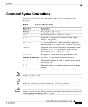
... should hold down the Control key while you solve a problem. Examples of data. 78-18039-02 Catalyst 4900 Series Switch Installation Guide xi Nonprinting characters, such as passwords, appear in square brackets. Default responses to system prompts appear in angled brackets. Tip Means the following information will help you press the D key. You...
... should hold down the Control key while you solve a problem. Examples of data. 78-18039-02 Catalyst 4900 Series Switch Installation Guide xi Nonprinting characters, such as passwords, appear in square brackets. Default responses to system prompts appear in angled brackets. Tip Means the following information will help you press the D key. You...
Installation Guide
Page 23
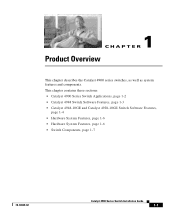
1 C H A P T E R Product Overview This chapter describes the Catalyst 4900 series switches, as well as system features and components. This chapter contains these sections: • Catalyst 4900 Series Switch Applications, page 1-2 • Catalyst 4948 Switch Software Features, page 1-3 • Catalyst 4948-10GE and Catalyst 4928-10GE Switch Software Features, page 1-4 • Hardware System Features, page 1-6 • Hardware System Features, page 1-6 • Switch Components, page 1-7 78-18039-02 Catalyst 4900 Series Switch Installation Guide 1-1
1 C H A P T E R Product Overview This chapter describes the Catalyst 4900 series switches, as well as system features and components. This chapter contains these sections: • Catalyst 4900 Series Switch Applications, page 1-2 • Catalyst 4948 Switch Software Features, page 1-3 • Catalyst 4948-10GE and Catalyst 4928-10GE Switch Software Features, page 1-4 • Hardware System Features, page 1-6 • Hardware System Features, page 1-6 • Switch Components, page 1-7 78-18039-02 Catalyst 4900 Series Switch Installation Guide 1-1
Installation Guide
Page 28
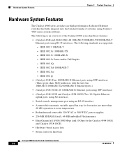
... 1 Product Overview Hardware System Features The Catalyst 4900 series switches are supported: - IEEE 802.1p • (Catalyst 4948) Four 1000BASE-X Ethernet ports using SFP interfaces (These ports share MAC addresses with the last four 10BASE-T/100BASE-TX/1000BASE-T Ethernet ports.) • (Catalyst 4928-10GE) 28 1000BASE-X Ethernet ports using SFP interfaces • (Catalyst 4948-10GE and Catalyst 4928-10GE) Two 10-Gigabit...
... 1 Product Overview Hardware System Features The Catalyst 4900 series switches are supported: - IEEE 802.1p • (Catalyst 4948) Four 1000BASE-X Ethernet ports using SFP interfaces (These ports share MAC addresses with the last four 10BASE-T/100BASE-TX/1000BASE-T Ethernet ports.) • (Catalyst 4928-10GE) 28 1000BASE-X Ethernet ports using SFP interfaces • (Catalyst 4948-10GE and Catalyst 4928-10GE) Two 10-Gigabit...
Installation Guide
Page 32
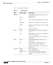
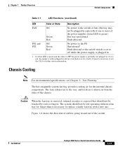
... 1-1 LED Functions LED STATUS Color or State Green Description At startup, the switch performs a series of diagnostic tests: All tests pass Red A test other than an individual port test fails Flashing System boot or diagnostic tests in progress Yellow System is in rommon mode or a power supply has failed CON MGT Port 1-48... this port Port is operational Port is disabled by user Power-on self-test indicates faulty port No signal detected or link configuration failure 1-10 Catalyst 4900 Series Switch Installation Guide 78-18039-02
... 1-1 LED Functions LED STATUS Color or State Green Description At startup, the switch performs a series of diagnostic tests: All tests pass Red A test other than an individual port test fails Flashing System boot or diagnostic tests in progress Yellow System is in rommon mode or a power supply has failed CON MGT Port 1-48... this port Port is operational Port is disabled by user Power-on self-test indicates faulty port No signal detected or link configuration failure 1-10 Catalyst 4900 Series Switch Installation Guide 78-18039-02
Installation Guide
Page 33
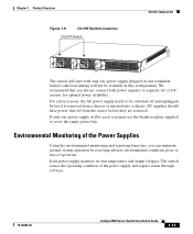
... air is probably not plugged in from the sides of the switch. 78-18039-02 Catalyst 4900 Series Switch Installation Guide 1-11 It may not be plugged in especially if one . Chassis Cooling Note For environmental specifications, see Chapter 2, "Site Planning." The system should not be left operating without a fan tray for longer than...
... air is probably not plugged in from the sides of the switch. 78-18039-02 Catalyst 4900 Series Switch Installation Guide 1-11 It may not be plugged in especially if one . Chassis Cooling Note For environmental specifications, see Chapter 2, "Site Planning." The system should not be left operating without a fan tray for longer than...
Installation Guide
Page 35
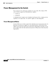
We recommend that you can maintain normal system operation by resolving adverse environmental conditions prior to be switched off from a chassis or inserted into a chassis. Each power supply monitors its own temperature and output voltages. For safety reasons...needs to loss of operation. Environmental Monitoring of the power supply and reports status through software. 78-18039-02 Catalyst 4900 Series Switch Installation Guide 1-13 The switch senses the operating condition of the Power Supplies Using the environmental monitoring and reporting functions, you always connect both ...
We recommend that you can maintain normal system operation by resolving adverse environmental conditions prior to be switched off from a chassis or inserted into a chassis. Each power supply monitors its own temperature and output voltages. For safety reasons...needs to loss of operation. Environmental Monitoring of the power supply and reports status through software. 78-18039-02 Catalyst 4900 Series Switch Installation Guide 1-13 The switch senses the operating condition of the Power Supplies Using the environmental monitoring and reporting functions, you always connect both ...
Installation Guide
Page 36
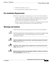
... power supply fails, the other unit increases power to 45/55 percent of the total system power requirements at all times. In this mode, if both power supplies are interchangeable. The Catalyst 4900 series switches support the following power supplies: • 300 W AC • 300 W DC ...A redundant power supply can choose AC or DC power supplies for the Switch You can be identified and diagnosed by a running system regardless of its input status....
... power supply fails, the other unit increases power to 45/55 percent of the total system power requirements at all times. In this mode, if both power supplies are interchangeable. The Catalyst 4900 series switches support the following power supplies: • 300 W AC • 300 W DC ...A redundant power supply can choose AC or DC power supplies for the Switch You can be identified and diagnosed by a running system regardless of its input status....

Installation Guide
Page 37
...Catalyst 4900 Series Switch Installation Guide 2-1 Site Environmental Requirements Planning a proper location for the switch and layout for your site for successful system operation. Equipment that is placed too closely together or that you complete all site planning activities before you install the switch.... In addition, poor equipment placement can cause system overtemperature conditions. Note A site planning checklist is inadequately ventilated can make chassis panels inaccessible...
...Catalyst 4900 Series Switch Installation Guide 2-1 Site Environmental Requirements Planning a proper location for the switch and layout for your site for successful system operation. Equipment that is placed too closely together or that you complete all site planning activities before you install the switch.... In addition, poor equipment placement can cause system overtemperature conditions. Note A site planning checklist is inadequately ventilated can make chassis panels inaccessible...

Installation Guide
Page 38
..., clean, well-ventilated, and air-conditioned environment. Cooling air is drawn in Appendix A are those within which the switch will continue to 104° F). To maintain normal operation and ensure high system availability, maintain an ambient temperature and EMI-free and continuous power at your site power before you install the... chassis. however, a measurement that approaches the minimum or maximum of the following sections: • Pre-installation Requirements, page 2-3 • Warnings and Cautions, page 2-3 Catalyst 4900 Series Switch Installation Guide 2-2 78-18039-02
..., clean, well-ventilated, and air-conditioned environment. Cooling air is drawn in Appendix A are those within which the switch will continue to 104° F). To maintain normal operation and ensure high system availability, maintain an ambient temperature and EMI-free and continuous power at your site power before you install the... chassis. however, a measurement that approaches the minimum or maximum of the following sections: • Pre-installation Requirements, page 2-3 • Warnings and Cautions, page 2-3 Catalyst 4900 Series Switch Installation Guide 2-2 78-18039-02
Installation Guide
Page 39
... before connecting the system to all national laws and regulations. provide each switch with its own branch circuit connection with local and national electrical codes. An overload of input power can result if this product should be handled according to the power source. Statement 1040 78-18039-02 Catalyst 4900 Series Switch Installation Guide...
... before connecting the system to all national laws and regulations. provide each switch with its own branch circuit connection with local and national electrical codes. An overload of input power can result if this product should be handled according to the power source. Statement 1040 78-18039-02 Catalyst 4900 Series Switch Installation Guide...
Installation Guide
Page 40
...create an electrical hazard by conducting power surges through lines and into equipment. Catalyst 4900 Series Switch Installation Guide 2-4 78-18039-02 When planning the location of the new system, consider electromagnetic interface (EMI), the distance limitations for an installation. Heat ...air-conditioning requirements for signaling, and connector compatibility. When wires are run for planning the power distribution system needed to support the switches. Power Requirements and Heat Dissipation The power requirements might need to Appendix A, "Specifications," for the power ...
...create an electrical hazard by conducting power surges through lines and into equipment. Catalyst 4900 Series Switch Installation Guide 2-4 78-18039-02 When planning the location of the new system, consider electromagnetic interface (EMI), the distance limitations for an installation. Heat ...air-conditioning requirements for signaling, and connector compatibility. When wires are run for planning the power distribution system needed to support the switches. Power Requirements and Heat Dissipation The power requirements might need to Appendix A, "Specifications," for the power ...
Installation Guide
Page 42
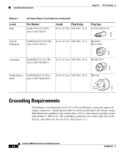
... VAC, 10 A BS 546 203795 Grounding Requirements Grounding is recommended on the right side of the chassis, and either one may be used. (See Figure 2-1.) Catalyst 4900 Series Switch Installation Guide 2-6 78-18039-02 Attach the provided two hole ground lug to the central office (CO) or other interior ground...
... VAC, 10 A BS 546 203795 Grounding Requirements Grounding is recommended on the right side of the chassis, and either one may be used. (See Figure 2-1.) Catalyst 4900 Series Switch Installation Guide 2-6 78-18039-02 Attach the provided two hole ground lug to the central office (CO) or other interior ground...
Installation Guide
Page 44
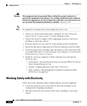
.... Avoid wearing any loose clothing, or securely fasten items such as ties, scarves, or sleeves. • Install the system in compliance with any electrical equipment: • Locate the emergency power-off of a suitably installed ground conductor. Never defeat...you are working with the following local and national electrical codes: - United States-National Fire Protection Association (NFPA 70); Catalyst 4900 Series Switch Installation Guide 2-8 78-18039-02 Safety Overview Chapter 2 Site Planning Warning This equipment must be grounded. Canada-Canadian Electrical...
.... Avoid wearing any loose clothing, or securely fasten items such as ties, scarves, or sleeves. • Install the system in compliance with any electrical equipment: • Locate the emergency power-off of a suitably installed ground conductor. Never defeat...you are working with the following local and national electrical codes: - United States-National Fire Protection Association (NFPA 70); Catalyst 4900 Series Switch Installation Guide 2-8 78-18039-02 Safety Overview Chapter 2 Site Planning Warning This equipment must be grounded. Canada-Canadian Electrical...
Installation Guide
Page 48
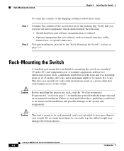
... the front and rear mounting posts of 19.25 inches (48.9 cm), and a maximum depth of the accessories kit to the system and components. Catalyst 4900 Series Switch Installation Guide 3-2 78-18039-02 Do not stack more than two on page 3-2. Rack-Mounting the... Switch A standard rack-mount kit is not intended to the switch. Rack-Mounting the Switch Chapter 3 Installing the Switch To verify the contents of the shipping container follow these steps: Step...
... the front and rear mounting posts of 19.25 inches (48.9 cm), and a maximum depth of the accessories kit to the system and components. Catalyst 4900 Series Switch Installation Guide 3-2 78-18039-02 Do not stack more than two on page 3-2. Rack-Mounting the... Switch A standard rack-mount kit is not intended to the switch. Rack-Mounting the Switch Chapter 3 Installing the Switch To verify the contents of the shipping container follow these steps: Step...