
Installation Guide
Page 7
...13 Attaching the Optional Cable Guide 2-13 Installing the Switch on a Wall 2-15 Attaching the Brackets to the Switch 2-15 Attaching the Switch to a Wall 2-16 Installing the Switch on a Table or Shelf 2-17 Powering On the Switch and Running POST 2-17 Connecting to the 10/100... Terminal to the Console Port 2-23 Assigning Switch Information 2-24 Using the Setup Program 2-25 Using BOOTP 2-29 Default Configuration Settings 2-29 Where to Go Next 2-31 Troubleshooting 3-1 Understanding POST Results 3-2 Diagnosing Problems 3-3 Contents 78-6456-03 Catalyst 3500 Series XL Hardware Installation Guide vii
...13 Attaching the Optional Cable Guide 2-13 Installing the Switch on a Wall 2-15 Attaching the Brackets to the Switch 2-15 Attaching the Switch to a Wall 2-16 Installing the Switch on a Table or Shelf 2-17 Powering On the Switch and Running POST 2-17 Connecting to the 10/100... Terminal to the Console Port 2-23 Assigning Switch Information 2-24 Using the Setup Program 2-25 Using BOOTP 2-29 Default Configuration Settings 2-29 Where to Go Next 2-31 Troubleshooting 3-1 Understanding POST Results 3-2 Diagnosing Problems 3-3 Contents 78-6456-03 Catalyst 3500 Series XL Hardware Installation Guide vii
Installation Guide
Page 11
... with the concepts and terminology of the switches in the series, explains how to install a switch and set up its initial configuration, provides troubleshooting information, and describes how to assign IP information to the switch. 78-6456-04 Catalyst 3500 Series XL Hardware Installation Guide xi Purpose The Catalyst 3500 Series XL Hardware Installation Guide documents...
... with the concepts and terminology of the switches in the series, explains how to install a switch and set up its initial configuration, provides troubleshooting information, and describes how to assign IP information to the switch. 78-6456-04 Catalyst 3500 Series XL Hardware Installation Guide xi Purpose The Catalyst 3500 Series XL Hardware Installation Guide documents...

Installation Guide
Page 12
... in various languages of how the switch could be used to connect to the switch. Chapter 3, "Troubleshooting," describes how to identify and resolve some of the switch. Appendix A, "Technical Specifications," lists the physical and environmental specifications for installing a switch on a rack, wall, table...supply values are installing the switch. Chapter 2, "Installing and Starting Up the Switch," contains the procedures for the switches and the regulatory agency approvals. It also describes how to set up the switch initial configuration. Catalyst 3500 Series XL Hardware Installation...
... in various languages of how the switch could be used to connect to the switch. Chapter 3, "Troubleshooting," describes how to identify and resolve some of the switch. Appendix A, "Technical Specifications," lists the physical and environmental specifications for installing a switch on a rack, wall, table...supply values are installing the switch. Chapter 2, "Installing and Starting Up the Switch," contains the procedures for the switches and the regulatory agency approvals. It also describes how to set up the switch initial configuration. Catalyst 3500 Series XL Hardware Installation...
Installation Guide
Page 20
...Cisco.com features the Cisco TAC website as an online starting point for troubleshooting and resolving technical issues with Cisco products and technologies. The Cisco TAC website is available 24 hours a day, 365 days a year. Accessing all customers, partners, resellers, and distributors who hold valid Cisco service contracts, the Cisco...-winning technical support services, online and over the phone. On the Cisco Documentation home page, click Feedback at this URL: http://tools.cisco.com/RPF/register/register.do Catalyst 3500 Series XL Hardware Installation Guide xx 78-6456-04 You can ...
...Cisco.com features the Cisco TAC website as an online starting point for troubleshooting and resolving technical issues with Cisco products and technologies. The Cisco TAC website is available 24 hours a day, 365 days a year. Accessing all customers, partners, resellers, and distributors who hold valid Cisco service contracts, the Cisco...-winning technical support services, online and over the phone. On the Cisco Documentation home page, click Feedback at this URL: http://tools.cisco.com/RPF/register/register.do Catalyst 3500 Series XL Hardware Installation Guide xx 78-6456-04 You can ...
Installation Guide
Page 22
... business operations. You can access Packet magazine at this URL: xxii Catalyst 3500 Series XL Hardware Installation Guide 78-6456-04 You can access iQ Magazine at this URL: http://www.cisco.com/go/packet • iQ Magazine is available from their networking ... involved in -depth online resources. Included are networking deployment and troubleshooting tips, configuration examples, customer case studies, tutorials and training, certification information, and links to Cisco Press online at this URL: http://www.cisco.com/go to numerous in designing, developing, and operating public ...
... business operations. You can access Packet magazine at this URL: xxii Catalyst 3500 Series XL Hardware Installation Guide 78-6456-04 You can access iQ Magazine at this URL: http://www.cisco.com/go/packet • iQ Magazine is available from their networking ... involved in -depth online resources. Included are networking deployment and troubleshooting tips, configuration examples, customer case studies, tutorials and training, certification information, and links to Cisco Press online at this URL: http://www.cisco.com/go to numerous in designing, developing, and operating public ...
Installation Guide
Page 76
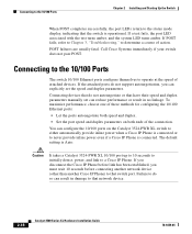
If POST fails, refer to Chapter 3, "Troubleshooting," to a Cisco IP Phone. The default setting is operational. Failure to do not support autonegotiation, you must wait 10 seconds before connecting another network device (other than another Cisco IP Phone) to that the switch is Auto. If a test fails, the .... • Set the port speed and duplex parameters on the Catalyst 3524-PWR XL switch to either automatically provide inline power when a Cisco IP Phone is connected or to never provide inline power even if a Cisco IP Phone is connected. POST failures are usually fatal. Caution It...
If POST fails, refer to Chapter 3, "Troubleshooting," to a Cisco IP Phone. The default setting is operational. Failure to do not support autonegotiation, you must wait 10 seconds before connecting another network device (other than another Cisco IP Phone) to that the switch is Auto. If a test fails, the .... • Set the port speed and duplex parameters on the Catalyst 3524-PWR XL switch to either automatically provide inline power when a Cisco IP Phone is connected or to never provide inline power even if a Cisco IP Phone is connected. POST failures are usually fatal. Caution It...
Installation Guide
Page 78
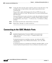
... (STP) discovers the topology and searches for solutions to cabling problems. Reconfigure and reboot the connected device if necessary. See Chapter 3, "Troubleshooting," for loops. For detailed instructions on page 1-9, and then connect to the 1000BaseX ports. Connecting to the GBIC Module Ports Note Install...Installation Guide. 2-20 Catalyst 3500 Series XL Hardware Installation Guide 78-6456-04 If the port LED does not come on, the device at the other device. Repeat steps 1 through 3 to connect each device. For detailed instructions on when both the switch and the connected ...
... (STP) discovers the topology and searches for solutions to cabling problems. Reconfigure and reboot the connected device if necessary. See Chapter 3, "Troubleshooting," for loops. For detailed instructions on page 1-9, and then connect to the 1000BaseX ports. Connecting to the GBIC Module Ports Note Install...Installation Guide. 2-20 Catalyst 3500 Series XL Hardware Installation Guide 78-6456-04 If the port LED does not come on, the device at the other device. Repeat steps 1 through 3 to connect each device. For detailed instructions on when both the switch and the connected ...

Installation Guide
Page 91
.... See the Cisco IOS Desktop Switching Software Configuration Guide, the Cisco IOS Desktop Switching Command Reference (online only), or the documentation that came with your SNMP application for troubleshooting problems: • Understanding POST results • Diagnosing problems 78-6456-04 Catalyst 3500 Series XL.... This chapter describes the following topics for details. For a full description of the switch LEDs, see the "LEDs" section on self-test (POST), port-connectivity problems, and overall switch performance. CH A P T E R 3 Troubleshooting The LEDs on the front panel provide...
.... See the Cisco IOS Desktop Switching Software Configuration Guide, the Cisco IOS Desktop Switching Command Reference (online only), or the documentation that came with your SNMP application for troubleshooting problems: • Understanding POST results • Diagnosing problems 78-6456-04 Catalyst 3500 Series XL.... This chapter describes the following topics for details. For a full description of the switch LEDs, see the "LEDs" section on self-test (POST), port-connectivity problems, and overall switch performance. CH A P T E R 3 Troubleshooting The LEDs on the front panel provide...
Installation Guide
Page 92
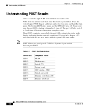
...display, indicating that the switch is powered on. Call Cisco Systems if your switch does not pass POST. Understanding POST Results Chapter 3 Troubleshooting Understanding POST Results Table 3-1 lists the eight POST tests and their associated LEDs. When the switch begins POST, the port...each time the switch is operational. Table 3-1 POST Test Descriptions Switch LED LED 1 LED 2 LED 3 LED 4 LED 5 LED 6 LED 7 LED 8 Component Tested DRAM Flash memory Switch CPU System board CPU interface ASIC Switch core ASIC Ethernet controller ASIC Ethernet interfaces Catalyst 3500 Series XL ...
...display, indicating that the switch is powered on. Call Cisco Systems if your switch does not pass POST. Understanding POST Results Chapter 3 Troubleshooting Understanding POST Results Table 3-1 lists the eight POST tests and their associated LEDs. When the switch begins POST, the port...each time the switch is operational. Table 3-1 POST Test Descriptions Switch LED LED 1 LED 2 LED 3 LED 4 LED 5 LED 6 LED 7 LED 8 Component Tested DRAM Flash memory Switch CPU System board CPU interface ASIC Switch core ASIC Ethernet controller ASIC Ethernet interfaces Catalyst 3500 Series XL ...
Installation Guide
Page 93
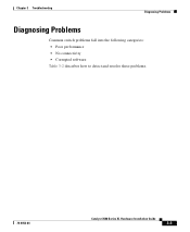
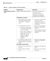
Chapter 3 Troubleshooting Diagnosing Problems Diagnosing Problems Common switch problems fall into the following categories: • Poor performance • No connectivity • Corrupted software Table 3-2 describes how to detect and resolve these problems. 78-6456-04 Catalyst 3500 Series XL Hardware Installation Guide 3-3
Chapter 3 Troubleshooting Diagnosing Problems Diagnosing Problems Common switch problems fall into the following categories: • Poor performance • No connectivity • Corrupted software Table 3-2 describes how to detect and resolve these problems. 78-6456-04 Catalyst 3500 Series XL Hardware Installation Guide 3-3
Installation Guide
Page 94
... Desktop Switching Software Configuration Guide for cabling guidelines. • For 10BaseT connections: The distance between the port and the attached device exceeds 100 meters. • Reduce the cable length to within the recommended distances. Diagnosing Problems Chapter 3 Troubleshooting Table ...collision, or alignment errors. • See the Cisco IOS Desktop Switching Software Configuration Guide for LED to within the recommended distances. Catalyst 3500 Series XL Hardware Installation Guide 3-4 78-6456-04 If the switch is attached to a repeater, the total distance ...
... Desktop Switching Software Configuration Guide for cabling guidelines. • For 10BaseT connections: The distance between the port and the attached device exceeds 100 meters. • Reduce the cable length to within the recommended distances. Diagnosing Problems Chapter 3 Troubleshooting Table ...collision, or alignment errors. • See the Cisco IOS Desktop Switching Software Configuration Guide for LED to within the recommended distances. Catalyst 3500 Series XL Hardware Installation Guide 3-4 78-6456-04 If the switch is attached to a repeater, the total distance ...
Installation Guide
Page 95
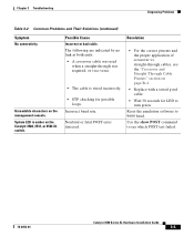
Unreadable characters on the Catalyst 3508, 3512, or 3524 XL switch. The following are indicated by no link at both ends: • A crossover cable was required, or vice-versa. • The cable is amber on the management console. Nonfatal or fatal POST error detected. Chapter 3 Troubleshooting Diagnosing Problems Table 3-2 Common Problems and Their Solutions...
Unreadable characters on the Catalyst 3508, 3512, or 3524 XL switch. The following are indicated by no link at both ends: • A crossover cable was required, or vice-versa. • The cable is amber on the management console. Nonfatal or fatal POST error detected. Chapter 3 Troubleshooting Diagnosing Problems Table 3-2 Common Problems and Their Solutions...

Installation Guide
Page 96
...Cisco IP Phone. The Catalyst 3524-PWR XL switch can operate normally with one failed fan. Make sure the switch is connected to the LAN-to check if an overtemperature condition exists. Resolution • Either check the switch itself or use the show env command to -phone jack on Improper cabling. Diagnosing Problems Chapter 3 Troubleshooting... Table 3-2 Common Problems and Their Solutions (continued) Symptom System LED is amber on the switch has failed. Catalyst 3500 Series XL Hardware Installation Guide 3-6 78...
...Cisco IP Phone. The Catalyst 3524-PWR XL switch can operate normally with one failed fan. Make sure the switch is connected to the LAN-to check if an overtemperature condition exists. Resolution • Either check the switch itself or use the show env command to -phone jack on Improper cabling. Diagnosing Problems Chapter 3 Troubleshooting... Table 3-2 Common Problems and Their Solutions (continued) Symptom System LED is amber on the switch has failed. Catalyst 3500 Series XL Hardware Installation Guide 3-6 78...
Installation Guide
Page 155
...document conventions xii duplex LED 1-17, 1-18 E electrical noise, avoiding 2-8 electromagnetic interference (EMI) A-3 EMC regulatory statements 2-5 Enterprise Edition software, switches running 1-2 examples, network configuration 1-25 F features 1-1 to 1-3 flooding, traffic control 2-30 front panel 1-5 to 1-20 10/100 ports 1-7 ...humidity A-1, A-2, A-3 I IEEE 802.1p 1-3 inline power 1-8, 2-18 to 2-19 LED 1-17, 1-19 troubleshooting 3-6 installation guidelines 2-7 rack-mount 2-9 See also procedures warning C-9 Inter-Switch Link (ISL) 1-3 Catalyst 3500 Series XL Hardware Installation Guide IN-3
...document conventions xii duplex LED 1-17, 1-18 E electrical noise, avoiding 2-8 electromagnetic interference (EMI) A-3 EMC regulatory statements 2-5 Enterprise Edition software, switches running 1-2 examples, network configuration 1-25 F features 1-1 to 1-3 flooding, traffic control 2-30 front panel 1-5 to 1-20 10/100 ports 1-7 ...humidity A-1, A-2, A-3 I IEEE 802.1p 1-3 inline power 1-8, 2-18 to 2-19 LED 1-17, 1-19 troubleshooting 3-6 installation guidelines 2-7 rack-mount 2-9 See also procedures warning C-9 Inter-Switch Link (ISL) 1-3 Catalyst 3500 Series XL Hardware Installation Guide IN-3
Installation Guide
Page 158
...slots See ports 1-9 SNMP network management platforms 1-3, 1-25 software by model 1-2 software switch management 1-24 specifications A-1 stacking the chassis warning C-13 standard edition software, switches running 1-2 startup powering on 2-17 straight-through cable pinouts B-4 SunNet Manager 1-25 ... accessing the CLI 1-25 temperature operating A-1 warning C-16 terminal, connecting to switch 2-23 terminal emulation software 2-23 TN power warning C-19 translated warnings C-1 troubleshooting 3-1 to 3-5 U UTL LED 1-16, 1-17 IN-6 Catalyst 3500 Series XL Hardware Installation Guide 78-6456-04
...slots See ports 1-9 SNMP network management platforms 1-3, 1-25 software by model 1-2 software switch management 1-24 specifications A-1 stacking the chassis warning C-13 standard edition software, switches running 1-2 startup powering on 2-17 straight-through cable pinouts B-4 SunNet Manager 1-25 ... accessing the CLI 1-25 temperature operating A-1 warning C-16 terminal, connecting to switch 2-23 terminal emulation software 2-23 TN power warning C-19 translated warnings C-1 troubleshooting 3-1 to 3-5 U UTL LED 1-16, 1-17 IN-6 Catalyst 3500 Series XL Hardware Installation Guide 78-6456-04